


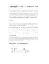
5. Double check your work.
We use the DTR (pin 4 on the female connector) as our +5 volts power for
the circuit. It is used as the Vcc pull-up voltage for testing the outputs on
any “UPS by APC” in voltage-signalling mode. This cable may not work on
a BackUPS Pro if the default communications are in apcsmart mode. This
cable is also valid for “ShareUPS” BASIC Port mode and is also reported to
work on SmartUPSes. However, the Smart Cable described above is much
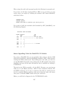
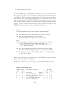
simpler. To have a better idea of what is going on inside apcupsd, for the
SIMPLE cable apcupsd reads three signals and sets three:
Reads:
CD, which apcupsd uses for the On Battery signal when high.
CTS, which apcupsd uses for the Battery Low signal when high.
RxD (SR), which apcupsd uses for the Line Down
signal when high. This signal isn’t used for much.
Sets:
DTR, which apcupsd sets when it detects a power failure (generally
5 to 10 seconds after the CD signal goes high). It
clears this signal if the CD signal subsequently goes low
-- i.e. power is restored.
TxD (ST), which apcupsd clears when it detects that the CD signal
has gone low after having gone high - i.e. power is restored.
RTS, which apcupsd sets for the killpower signal -- to cause the UPS
to shut off the power.
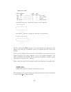
Please note that these actions apply only to the SIMPLE cable, the signals
used on the other cables are different.
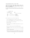
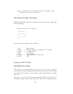
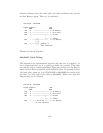
Finally, here is another way of looking at the CUSTOM-SIMPLE cable:
APCUPSD SIMPLE-CUSTOM CABLE
Computer Side | Description of Cable | UPS Side
DB9f | DB25f | | DB9m | DB25m
4 | 20 | DTR (5vcc) *below | n/c |
8 | 5 | CTS (low battery) *below | <- 5 | 7
2 | 3 | RxD (no line voltage) *below | <- 3 | 2
5 | 7 | Ground (Signal) | 4 | 20
1 | 8 | CD (on battery from UPS) | <- 2 | 3
7 | 4 | RTS (kill UPS power) | -> 1 | 8
140