


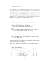
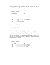
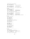
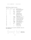
BackOffice ES:
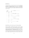
The BackUPS ES has a straight through serial cable with no identification
on the plugs. To make it work with apcupsd, specify the UPSCABLE
940-0119A and UPSTYPE backups. The equivalent of cable 940-0119A
is done on a PCB inside the unit. Thanks to William Stock for supplying
us with the information about the straight through cable, the PCB, and the
following diagram:
computer ----------- BackUPS-ES -----------------
DB9-M DB-9F
pin signal pin
4 DSR -> 4 --+
| diode resistor
6 DTR -> 6 --+---->|----/\/\/\---o kill power
1 DCD <- 1 --+
|
2 RxD <- 2 --+----------------+--o low battery
|
7 RTS -> 7 --------+--/\/\/\--+
|
+--/\/\/\--+
|
8 RI <- 8 --+----------------+--o on battery
|
9 CTS <- 9 --+
5 GND --- 5 ----------------------o ground
3 TxD 3 nc
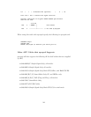
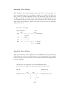
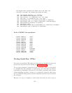
BackUPS ES and CS in Serial mode with Cable 940-0128A:
Though these UPSes are USB UPSes, APC supplies a serial cable (typically
with a green DB9 F connector) that has 940-0128A stamped into one side of
the plastic serial port connector. The other end of the cable is a 10 pin RJ45
connector that plugs into the UPS (thanks to Dean Waldow for sending me a
cable!). Apcupsd version 3.8.5 and later supports this cable when specified as
UPSCABLE 940-0128A and UPSTYPE backups. However, running
in this mode much of the information that would be available in USB mode
is lost. In addition, when apcupsd attempts to instruct the UPS to kill the
power, it begins cycling about 4 times a second between battery and line.
148