


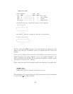
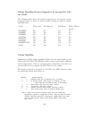

CUSTOM-RJ45 CABLE
Signal Computer UPS UPS
DB9F RJ45-8 RJ45-10
RxD 2 ---------------- 1 2 TxD Send
TxD 3 ---------------- 7 8 RxD Receive
GND 5 ---------------- 6 7 Ground
FG Shield ---------------- 3 4 Frame Ground
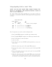
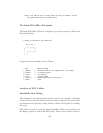
The RJ45-8 pins are: looking at the end of the connector:
8 7 6 5 4 3 2 1
___________________
| . . . . . . . . |
| |
-------------------
|____|
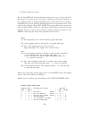
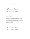
The RJ45-10 pins are: looking at the end of the connector:
10 9 8 7 6 5 4 3 2 1
_______________________
| . . . . . . . . . . |
| |
-----------------------
|____|
For the serial port DB9F connector, the pin numbers are stamped in the
plastic near each pin. In addition, there is a diagram near the end of this
chapter.
Note, one user, Martin, has found that if the shield is not connected to the
Frame Ground in the above diagram (not in our original schematic), the
UPS (a BackUPS CS 500 EI) will be unstable and likely to rapidly switch
from power to batteries (i.e. chatter).
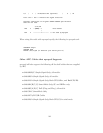
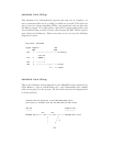
When using this cable with apcupsd specify the following in apcupsd.conf:
UPSCABLE smart
UPSTYPE apcsmart
DEVICE /dev/ttyS0 (or whatever your serial port is)
The information for constructing this cable was discovered and transmitted
to us by slither man. Many thanks!
138