


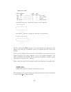
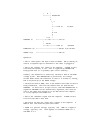
| B |
*-------| 2N3906 PNP
|
|\
\ C
|
|
*----< DCD (1) Low Batt
|
|
R 4.7k
3
|
4.7k |
SHUTDOWN (1) >----------*----R4----*----< TxD (3)
|
| 1N4148
*----K|---------< RTS (7) Shutdown
POWER-FAIL (2) >--------------------------< RxD,RI (2,9) On Batt
GROUND (4,9) >--------------------------< GND (5)
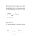
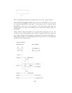
Operation:
* DTR is "cable power" and must be held at SPACE. DSR or CTS may be
used as a loopback input to determine if the cable is plugged in.
* DCD is the "battery low" signal to the computer. A SPACE on this
line means the battery is low. This is signalled by BATTERY-LOW
being pulled down (it is probably open circuit normally).
Normally, the transistor is turned off, and DCD is held at the MARK
voltage by TxD. When BATTERY-LOW is pulled down, the voltage
divider R2/R1 biases the transistor so that it is turned on, causing
DCD to be pulled up to the SPACE voltage.
* TxD must be held at MARK; this is the default state when no data is
being transmitted. This sets the default bias for both DCD and
SHUTDOWN. If this line is an open circuit, then when BATTERY-LOW is
signalled, SHUTDOWN will be automatically signalled; this would be
true if the cable were plugged in to the UPS and not the computer,
or if the computer were turned off.
* RTS is the "shutdown" signal from the computer. A SPACE on this
line tells the UPS to shut down.
* RxD and RI are both the "power-fail" signals to the computer. A
MARK on this line means the power has failed.
* SPACE is a positive voltage, typically +12V. MARK is a negative
voltage, typically -12V. Linux appears to translate SPACE to a 1
and MARK to a 0.
146