


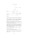
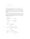
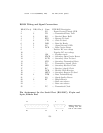
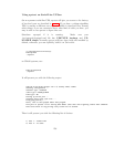
The diagram above represents the Female end of the cable. The
male end is the same, but looking from inside the cable.
DTE : Data Terminal Equipment (i.e. computer)
DCE : Data Communications Equipment (i.e. UPS)
RxD : Data received; 1 is transmitted "low", 0 as "high"
TxD : Data sent; 1 is transmitted "low", 0 as "high"
DTR : DTE announces that it is powered up and ready to communicate
DSR : DCE announces that it is ready to communicate; low=modem hang-up
RTS : DTE asks DCE for permission to send data
CTS : DCE agrees on RTS
RI : DCE signals the DTE that an establishment of a connection is attempted
DCD : DCE announces that a connection is established
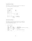
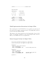
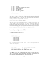
Ioctl to RS232 Correspondence
#define TIOCM_LE 0x001
#define TIOCM_DTR 0x002
#define TIOCM_RTS 0x004
#define TIOCM_ST 0x008
#define TIOCM_SR 0x010
#define TIOCM_CTS 0x020
#define TIOCM_CAR 0x040
#define TIOCM_RNG 0x080
#define TIOCM_DSR 0x100
#define TIOCM_CD TIOCM_CAR
#define TIOCM_RI TIOCM_RNG
#define TIOCM_OUT1 0x2000
#define TIOCM_OUT2 0x4000
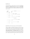
Testing Serial-Line UPSes
If you have a serial-line UPS, there are some tests you should run before the
general ones described in the Testing (see Testing Apcupsd) section.
To test your computer’s connection with a serial-line UPS, you first need
to establish that the serial line is functioning, and then that the UPS is
responding to commands. This can be a bit tricky, especially with a dumb
voltage-signalling interface, because it is completely quiescent when there
are no commands being passed, and the command repertoire doesn’t include
any self-tests.
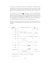
Because it is easy to configure a serial cable incorrectly in such a way as
154