


The solution to the problem (thanks to Tom Suzda) is to unplug the UPS
and while it is still chattering, press the power button (on the front of the
unit) until the unit beeps and the chattering stops. After that the UPS
should behave normally and power down 1-2 minutes after requested to do
so.
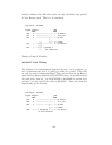
An amazing discovery by slither
man allows one to build a CUSTOM-RJ45
cable (documented above) and run the BackUPS CS (and probably also the
ES) in Smart mode. Running it this way provides all the same information
that you would get by running it in USB mode. As a consequence, we
recommend that you either purchase (where I don’t know) or build your
own CUSTOM-RJ45 cable rather than use the 940-0128A cable.
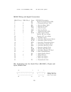
Thanks to all the people who have helped test this and have provided in-
formation on the cable wiring, our best guess for the cable schematic is the
following:
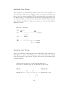
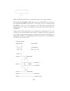
computer --------- Inside the Connector--------- UPS
DB9-F | | RJ45
pin - signal | | Pin - Color
| |
4 DSR ->|---+ |
| | diode resistor |
6 DTR ->|---+---->|----/\/\/\---o kill power | 8 Orange
| |
1 DCD <-|----+ |
| | |
2 RxD <-|----+----------------+--o low battery| 3 Brown
| | |
7 RTS ->|----------+--/\/\/\--+ |
| | |
| +--/\/\/\--+ |
| | |
8 RI <-|----+----------------+--o on battery | 2 Black
| | |
9 CTS <-|----+ |
| signal |
5 GND --|-----------------------o ground | 7 Red
| |
3 TxD | |
| chassis |
Chassis/GND |-----------------------o ground | 4 Black
| |
| Not connected | 1, 5, 6, 9, 10
--------------------------------------
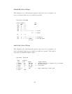
The RJ45 pins are: looking at the end of the connector:
10 9 8 7 6 5 4 3 2 1
149