


and information graciously supplied by APC. Hopefully, the additions made
herein can benefit the original author and his programming project, and
maybe some day, the apcupsd project and the NUT project can join forces.
Description
Here’s the information on the elusive APC smart signaling protocol used
by their higher end units (Back-UPS Pro, Smart-UPS, Matrix-UPS, etc).
What you see here has been collected from a variety of sources. Some people
analyzed the chatter between PowerChute and their hardware. Others sent
various characters to the UPS and figured out what the results meant.
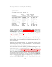
RS-232 differences
Normal 9 pin serial connections have TxD on 3 and RxD on 2. APC’s smart
serial ports put TxD on pin 1 and RxD on pin 2. This means you go nowhere
if you use a normal straight through serial cable. In fact, you might even
power down the load if you plug one of those cables in. This is due to the
odd routing of pins - DTR and RTS from the PC usually wind up driving
the on/off line. So, when you open the port, they go high and *poof* your
computer dies.
Originally this evil hack was used to connect the UPS to the PC when this
page was first being built. As you can see, I cheated and neglected the
ground (only 2 wires!) and it still worked. This method can be used for
playing around, but for professional systems this is obviously not a viable
option.
That hack didn’t work out so well (damned cats), so it was retired quite
awhile back. The most practical solution was to go out and BUY the
DOS/Win version of PowerChute just for the black (smart) cable. I rec-
ommend doing the same thing if you actually care about this thing working
properly. Of course, if you have one of the newer packages that came with
PowerChute, you already have the cable you need.
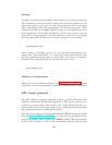
Diagram for cable hackers
If you are handy with cable creation tools, check out the
940-0024C clone diagram. That’s the black “smart” cable normally
provided with APC models sold after 1996. The loopback pins on that
187