


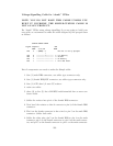
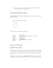
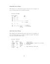
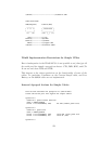
940-0095B Cable Wiring:
This diagram is for informational purposes and may not be complete, we
don’t recommend that use it to build one yourself.
APC Part# - 940-0095B
Signal Computer UPS
DB9F DB9M
DTR 4 ----*
CTS 8 ----|
DSR 6 ----|
DCD 1 ----*
GND 5 ---------------*---- 4 Ground
|
*---- 9 Common
RI 9 ----*
|
RxD 2 ----*--------------- 2 On Battery
TxD 3 ----------[####]---- 1 Kill UPS Power
4.7K ohm
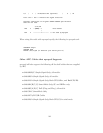
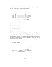
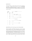
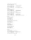
940-0119A Cable Wiring:
This diagram is for informational purposes and may not be complete, we
don’t recommend that use it to build you build one yourself. This cable is
used with the BackUPS Office UPSes.
APC Part# - 940-0119A
UPS Computer
pins pins Signal Signal meaning
1 (brown) 4,6 DSR DTR <- Shutdown when set by computer for 1-5 seconds.
2 (black) 8,9 RI CTS -> On battery power
3 (blue) 1,2 CD RxD -> Low battery
4 (red) 5 Ground
5 (yellow) 7 RTS <- Begin signalling on other pins
6 (none) none
147