


6-8 DISTRIBUTED COMMUNICATIONS SYSTEM (DCS)
_ ___________________________________________________________________________________________________________________________
_ ___________________________________________________________________________________________________________________________
_ ___________________________________________________________________________________________________________________________
DCS SIGNALING LINK CONNECTIONS
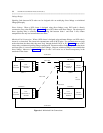
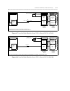
Many variables influence how the signaling channel on one DCS node is connected to the signaling channel
on another DCS node. Chief among these variables is the types of communications systems being
connected. For example, the System 75 and Generic 1 communications systems are connected differently
to other System 75s and Generic 1s than they are to System 85s and Generic 2s. Furthermore, within the
constraints imposed by the communications systems being connected are other constraints imposed by the
distance that the transmission must travel, the availability of digital trunks, the cost, etc. All these variables
must be considered when you decide how to connect the DCS signaling links. Illustrated next are the types
of connections possible given the types of communications systems being connected.
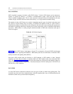
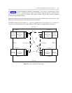
The connections are classified as long haul and short haul. Long haul connections have virtually no
distance limitations. Distance limitations on short haul connections are established by the types of data
sets/modules used. When you choose to use a particular type of connection, you should consider the
following distance limitations:
Equipment Distance Limitation
RS-232/RS-449 Link 50 ft
Isolating Data Interface (IDI) 400 ft.
Data Service Unit 2000 ft.
MTDM/MPDM 3500 ft.
DCP Link 5000 ft.
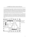
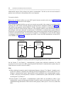
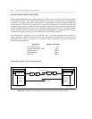
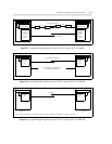
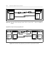
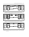
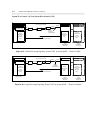
System 75 or Generic 1 (G1) to System 75 or G1
SIGNALING CHANNEL
ANALOG OR DS1 VOICE CHANNEL
MTDM
MTDM
DCP
DCP
TN764
(DIGITAL LINE)
PI
TN760
(TIE TRUNK)
TN722
OR TN767
(DS1)
TN764
(DIGITAL LINE)
PI
TN760
(TIE TRUNK)
TN722
OR TN767
(DS1)
DSU
DSU
SYSTEM 75/G1 SYSTEM 75/G1
Figure 6-6. Short Haul Analog Signaling: System 75/G1 to System 75/G1 Via DSU