


SYNCHRONIZATION OF DIGITAL FACILITIES B-29
_ ______________________________________________________________________________________
_ ______________________________________________________________________________________
_ ______________________________________________________________________________________
CONCLUSIONS ON SYNCHRONIZATION
Make no assumptions regarding synchronization. Reverify items such as the availability of a
synchronization source, the clock stratum, and compatibility of every T1 span. The best guarantee is
written confirmation that the local exchange carrier, AT&T Communications, or other vendor will either
synchronize to a System 75, System 85, Generic 1, Generic 2, or provide an appropriate synchronization
reference.
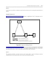
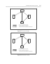
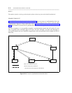
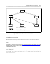
Develop a diagram showing the network synchronization plan. Make multiple copies of this diagram and
keep a copy at each switch site. This diagram is essential for installing, administering, and tuning up a DS1
network. Such a diagram can also be used by maintenance personnel to troubleshoot network problems
associated with synchronization.
A properly designed synchronization plan will improve the quality and reliability of a digital private
network. If designing a synchronization plan becomes too complex or if many applications have a crucial
dependency on the digital facilities, then the AT&T Qualnet Synchronization Design Service should be
consulted.
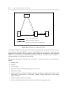
USE OF GENERIC 2 AS A SYSTEM CLOCK REFERENCE
To provide increased reliability, it is recommended that (for all cases) the primary and secondary system
clock references be placed in different modules. Tips on how best to use a DS1 as a clock reference are
provided next.
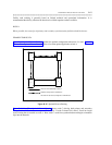
ISDN-PRI Trunk Facilities
ISDN-PRI trunks may terminate on a 4ESS toll office, 5ESS digital CO, System 85 R2V4, Generic 1,
Generic 2, or compatible vendor’s switch. Depending on other considerations, any of these terminating
connections may be selected as either a primary or secondary synchronization reference. ISDN-PRI
configurations may be established with an ANN35 or with a TN767 with or without a TN555, depending
upon the D-channel configuration of the TN767. A brief description of these three boards and their general
use for ISDN-PRI is given next.
The ANN11 is the DS1 board used with all System 85s and with traditional modules in Generic 2. The
ANN35 is the ISDN-PRI board used with System 85, R2V4, and Generic 2 traditional modules. The
TN767 is the DS1/ISDN-PRI board used with System 75, Generic 1, and Generic 2 universal modules.
The TN555 is the packet adjunct used with Generic 2 universal modules. If the TN767 has a D-channel on
it, it needs a TN555 located in the adjacent virtual slot.
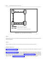
Line-Only Mode DS1/DMI-BOS (ANN11 or TN767)
When using a line-only mode interface for synchronization purposes, the following facts should be known:
• Since the D4-channel bank (or equivalent) at the far end will be timed to the signal received from a
DS1, no slips should occur on a line-only mode DS1 facility. Because of this, slip counts from line-