


TRANSMISSION STATES 1-9
_ ______________________________________________________________________________________
_ ______________________________________________________________________________________
_ ______________________________________________________________________________________
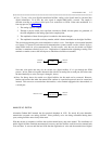
• Incoming digital-trunk calls to a digital switch need no conversion since the call is already PCM
encoded. Incoming digital-trunk calls to analog switches are converted outside the switch at a D4
channel bank. In these cases, the digital trunk terminates at the D4 channel bank. From the D4 channel
bank, incoming calls are forwarded to the switch via analog trunks. (See Multiplexed Communication
later in this chapter.)
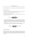
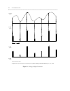
Inside a digital switch, therefore, voice is always coded as PCM. Inside an analog switch, voice is coded as
PAM for time-multiplexed switches or left as a pure analog signal for matrix switches.
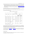
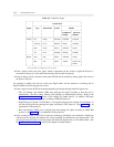
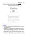
Below is a table that summarizes the types of signals that particular terminals generate and the types of
circuit packs that can handle the signals.
Table 1-1. Terminal/Port Compatibility
_ _______________________________________________________________________________
Circuit Packs
_ __________________________________________________________
Terminal Signal Type
DIMENSION S75/G1 S85/G2
_ ______________________
Traditional Universal
Module Module*
_ _______________________________________________________________________________
_ _______________________________________________________________________________
2500 series Analog Analog LC02 TN742 SN229 TN742
_ _______________________________________________________________________________
7100 series Analog Analog N/A TN742 SN229 TN742
_ _______________________________________________________________________________
7200 series Analog MFET LC02 & LC55 TN735 SN224 N/A
_ _______________________________________________________________________________
7300 series Analog MFAT N/A TN762 ANN17 TN762B
_ _______________________________________________________________________________
7400 series Digital Digital-line N/A TN754 SN270 TN754
or GPP
_ _______________________________________________________________________________
7500 series Digital BRI N/A N/A N/A TN556
_ _______________________________________________________________________________
* Universal modules are available only on the G2 switch.
Note that the table names the circuit-pack type by the type of terminal that can use it. Multifunction
electronic telephones use MFET circuit boards; multifunction analog telephones use MFAT circuit boards;
DCP terminals use digital ports (called digital-line ports on the S75/G1, and general-purpose ports [GPP]
on the S85/G2) and basic rate interface terminals use BRI ports.
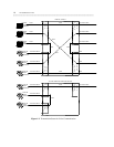
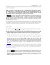
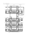
To complete the picture of analog and digital switch ports, you also need to know the trunk port types,
names, and numbers given in figure 1-2. (See the Trunking section of this chapter for an explanation of
trunk types and protocols.)
Exiting the Switch
For outgoing or tandem calls that are routed over analog trunks, and for intercom or incoming calls to
analog telephone sets, another conversion must occur.