


COMMUNICATIONS PROTOCOLS D-15
_ ______________________________________________________________________________________
_ ______________________________________________________________________________________
_ ______________________________________________________________________________________
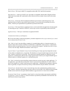
VARIABLE LENGTH
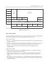
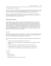
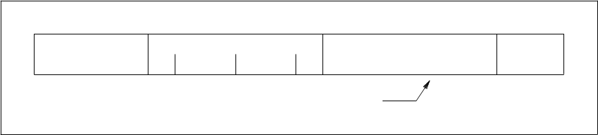
FLAG
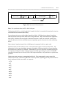
0 1 1 1 1 1 1 0 E SPARE SCA S DATA/CONTROL CRC
Figure D-4. Data mode 2 Frame Structure
Note: For asynchronous data, the SCA field is left spare.
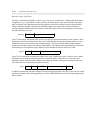
The data/control field is a variable length field. Length of the block is automatically determined by the data
rate and the desire to minimize transit delay.
For asynchronous data at any of the defined speeds from 300 to 19,200 bps where character boundaries
must be preserved, each byte in the block carries a single character. Only 8-bit characters are supported at
these speeds. Start/stop bits are stripped off before the character is coded into the block. Start/stop bits
must be added to the received (decoded) characters, depending upon the characteristics of the terminating
device.
Other character lengths and speeds below 1800 bps may be supported in the low-speed mode.
When the header status bit indicates control, control information appears in the data/control field. This
information is of two types: handshake and update. Handshake is performed after the call setup signaling
has finished and a connection is established. Handshake may also occur after data communications begins
if off-premises multispeed modem connections are involved and a speed change is required. Handshake
exchanges information such as bit rate, DCE or DTE endpoint definition, and synchronous or asynchronous
operation.
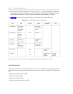
Update type control messages are transmitted periodically. They (transparently) convey status of the
interface control leads. The following RS-232C or their equivalent, depending upon the particular interface
that is configured with the data module, are supported:
• TM
• CI
• CE
• CC
• CF
• CB
• CH
• CN
• RL