


MULTIPLEXED COMMUNICATION 1-21
_ ______________________________________________________________________________________
_ ______________________________________________________________________________________
_ ______________________________________________________________________________________
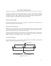
Signal Inversion
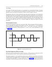
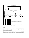
Signal inversion is the replacement of all 1s in a digital transmission stream with 0s; and the replacement of
all 0s with 1s. The use of signal inversion is related to the transmission facilities, the DMI mode, and the
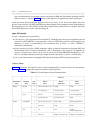
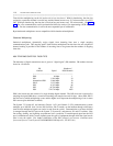
line coding. Table 1-6 gives the conditions under which a signal should be inverted. (The need for signal
inversion is given in the last three columns of the table. Note that when no inversion is necessary, the table
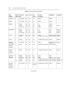
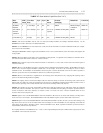
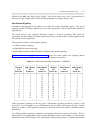
entry is "normal.") In addition, table 1-7 lists, among other things, AT&T data modules and their signal-
inversion capabilities. The tables assume the following knowledge of the difference between restricted
versus unrestricted channels; between bit-oriented signaling (BOS) and message-oriented signaling (MOS);
and among the DMI modes 0 through 3.
• Restricted channels are channels over which no all-zero bytes can be transmitted. The line equipment
transmitters on restricted channels use ZCS line coding.
Unrestricted channels have no restrictions on the number of consecutive zeros of user data that can be
transmitted. The line equipment transmitters on restricted channels use B8ZS line coding.
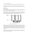
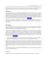
• Bit-oriented signaling is accomplished by inserting signaling bits in the 24th channel of a DS1 facility.
Message-oriented signaling is accomplished by inserting messaging octets in the 24th channel. (See
24th-Channel Signaling later in this chapter.)
Note that for BOS applications (and for any application where MOS is not carried end to end) the bearer
(B) channels should always be considered restricted since BOS cannot declare whether the network path
is restricted on a per-call basis.
• The DMI modes are explained in appendix D. Note that DMI mode-2 transmission is always inverted,
regardless of the facility.
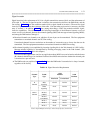
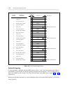
Table 1-6. Signal-Inversion Requirements
_ ________________________________________________________
1.544
Channel Traffic Facilities 2.048
Type Type
________________________
Facilities
Restricted Unrestricted
_ ________________________________________________________
_ ________________________________________________________
D BOS Normal Normal Normal
Channel Signaling
_ _______________________________________________
MOS Invert Normal Normal
Signaling
_ ________________________________________________________
Bearer Mode 0 Invert Normal Normal
Channel (HDLC)
_ _______________________________________________
Mode 0 Normal Normal Normal
(non-HDLC)
_ _______________________________________________
Mode 1 Normal Normal Normal
_ _______________________________________________
Mode 2 Invert Invert Invert
_ _______________________________________________
Mode 3 Invert Normal Normal
_ ________________________________________________________
Source: Digital Multiplexed Interface Technical Specification, 555-025-204