


MULTIPLEXED COMMUNICATION 1-25
_ ______________________________________________________________________________________
_ ______________________________________________________________________________________
_ ______________________________________________________________________________________
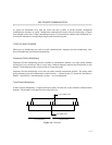
The framing format does not place any requirement on the type of signaling or line coding to be used.
However, the type of framing used at both ends of the DS1 transmission facility must be identical.
D4 Framing
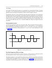
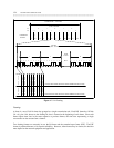
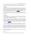
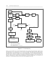
A synchronization pattern is a continuously repeating string that orients the receiving end to a frame’s
boundaries during a transmission. The D4 framing format uses a 12-bit fixed synchronization pattern
(100011011100). This 12-bit pattern is formed by the framing bit (the first bit) from 12 consecutive frames.
When the receiving port finds the pattern across the frames, it coincidentally has found the boundaries of
each frame, because the framing bit marks a frame’s beginning and end. The 12-frame unit that contains
the synchronization pattern is known as the D4 superframe. (See figure 1-7.)
D4 framing is supported by all equipment used with the System 75, System 85, Generic 1 and Generic 2
DS1, such as channel expansion multiplexers (CEMs), channel division multiplexers (CDMs), and D4
channel banks.
ESF Framing
The ESF framing format was developed after the D4 format. Not all equipment used with the DS1
interface supports ESF. Specifically, most D4 channel banks (unless they are configured as LIU-3ESF or
equivalent) and CDMs do not currently support ESF framing.
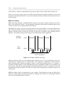
The synchronization pattern for the ESF format is formed by the framing bit from 24 consecutive frames.
Unlike the 12-bit synchronization pattern for D4, which utilizes all of the available framing bits for
synchronization, ESF employs only 6 of the available 24 framing bits to carry a synchronization pattern.
The other 18 framing bits form a 6-bit error-detection code, called the cyclic redundancy check (CRC) sum,
and a 12-bit facility data link signal. Each 24-frame entity, spanning one ESF cycle, is referred to as an
ESF superframe. (See figure 1-8.)
Note: The facility data link is a 4-kbps data link designed to maintain and supervise the DS1 facility.
However, this 4-kbps data link is not used by the System 75 and System 85 DS1 port boards.
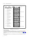
The CRC is used at the receive end to detect transmission errors, as follows: The CRC is calculated at the
transmit end and multiplexed into the DS1. At the receive end, the CRC is recalculated using the data in
the received ESF superframe and then compared with the received CRC. If the recalculated CRC and
received CRC do not match, a misframe is declared. The DS1 interface counts misframes and uses the
count for processing DS1 facility performance indicators, such as bit-error rates, major alarms, and minor
alarms.
The ESF reframing algorithm can find the synchronization pattern even if the time slots for the 24 channels
carry a bit sequence identical to it.
Signaling
The DS1 circuit pack can be administered to use either robbed-bit signaling or 24th-channel signaling.