


D-14 COMMUNICATIONS PROTOCOLS
_ ___________________________________________________________________________________________________________________________
_ ___________________________________________________________________________________________________________________________
_ ___________________________________________________________________________________________________________________________
Data Mode 2
Capabilities:
—Low, 300, 1200, 2400, 4800, 9600, or 19.2 kbps
—Full- or half-duplex operation
—Asynchronous transmission of user data, or
—Synchronous transmission (with clock independence)
—Requires a ‘‘circuit-switched’’ transmission facility
Note: The low-speed option permits operation at any data rate from 0 to 1800 bps. However, this option
uses a high-speed sampling technique and does not strictly preserve character boundaries.
Applications:
There exists a broad category of uses for mode 2. The most frequent is the support of data terminals.
However, these may also include the support of virtually all devices that are configured with one of the
following interfaces:
• RS-232C DTE/DCE or equivalent
• RS-449/423 DTE or equivalent
• V.35
Description:
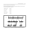
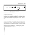
Mode 2 converts data (at standard data rates) to a format which can be transmitted over a DS0 (64-kbps)
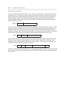
bearer channel. Mode-2 data is segmented into HDLC-type blocks. Each block is preceded with a flag and
header and then followed by a CRC checksum. Figure D-4 functionally depicts the mode-2 block structure.
User data is encoded into mode-2 format by a digital data module, digital voice terminal, or when analog
facilities are used by the port interface. The switch then routes the mode-2 data (I-channel) directly to
another port that serves a terminal, computer, DS1 facility, or DMI/BOS facility.
A single flag serves to both terminate a block and begin the next one. Also, multiple flags are used on an
active connection to idle the channel when there is no information to be sent.
The header is a minimum of 1 byte and may be extended with the (E) bit. The header indicates whether the
block is data (1) or control (0) by the state of the status (S) bit.
For synchronous transmission using data mode 2, a clock frequency adjustment technique is used. This
technique permits the transmission of synchronous data that is controlled by an external clock which is
independent of the DS1 or DMI/BOS facility. This technique allows passage of synchronous data whose
timing accuracy meets a minimum of ± 100 ppm (RS-334). The technique calls for sending synchronous
clock adjustment (SCA) bits in every block. This capability allows a data endpoint to compare the phase of
an external clock to the system clock derived from the DS1/DMI/BOS facility and, based on that
comparison, to request that phase adjustments be made in the clock at the remote data endpoint.