


8-24 PUBLIC AND PRIVATE DATA NETWORK CONNECTIONS
_ ___________________________________________________________________________________________________________________________
_ ___________________________________________________________________________________________________________________________
_ ___________________________________________________________________________________________________________________________
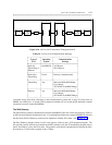
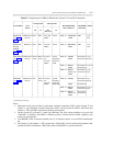
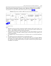
Table 8-6. Requirements for Connections from the PBX to SDS/SDDN
_ _______________________________________________________________________________________________
COMM TYPE TRUNK TYPE
FACILITIES CALL
_ __________________________________
RECOMMENDED NETWORK NOTES
SETUP DATA MODULE CHANNEL
S75 G1 S85 G2
_ _______________________________________________________________________________________________
_ _______________________________________________________________________________________________
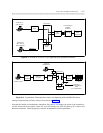
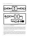
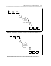
Robbed Bit Dial-up Data Data TT†=109 TT=41 Mode 1 = MPDM/M1* Restricted or 1,2,4,
through a (DMI) 7500B Unrestricted 5,6
DS1 (see
figure 8-14)
_ _______________________________________________________________________________________________
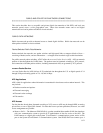
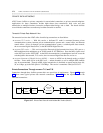
Domestic Dial-up N/A Data or TT=41 TT=41 Mode 0 = MPDM/M1* Restricted or 2,4,5
Network AVD Signaling Signaling 7500B Unrestricted 7,8,9
w/ISDN/PRI Type=20 Type=20
(see figure
8-15)
_ _________________________________________
Mode 1 = MPDM/M1* Restricted or 2,4,5,7
7500B Unrestricted
_ _________________________________________
Mode 2 = MPDM Restricted 3,4,5,7
7400A or B
_ _________________________________________
Mode 3 = PC/PBX Restricted 4
AUDIX
7500B 4,5
_ _______________________________________________________________________________________________
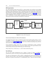
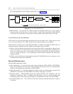
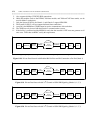
Intern’l Dial-up N/A N/A N/A ISDN-PRI Mode 0 = 7500B Unrestricted 4,5,8
Network TT=41 MPDM
w/ISDN-PRI Signaling
(see figure
_ ________________________
Type=20
_ _________________________________________
8-16) N/A Data or N/A Mode 1 = 7500B Restricted or 2,4
AVD MPDM Unrestricted
_ _______________________________________________________________________________________________
† TT stands for trunk type.
Notes:
1. On the System 85 or Generic 2, trunk type 109 (DMI) prohibits subnet trunking through AAR/ARS.
2. The MPDM requires a V.35 interface and an
ACCUNET SW56 modification kit.
3. Older data modules (such as DTDM, 7404 data module, and 7406 and 7407 data stands), can be used for mode-2
connections.
4. The bearer capability class of service must be set appropriately.
5. The 7500B can be used only with the Generic 2 communications system.
6. This connection can be made only from the System 85 (R2V3 or R2V4), Generic 2, Generic 1, and the System
75 (R1V2 or later).
7. This connection can be made only from a System 85 (R2V4), Generic 1, or Generic 2.
8. At mode 0, the MPDM and 7500B cannot be used to communicate with each other unless a bit inversion cable is
used.
9. If the facility is restricted and the MPDM is used, then the customer’s DTE should use uninverted HDLC. The
MPDM inverts mode 0 HDLC to satisfy the requirement that an all-zeros octet is never generated. If the DTE is
sending inverted HDLC, then the bit inversion cable should be used.