


B-18 SYNCHRONIZATION OF DIGITAL FACILITIES
_ ___________________________________________________________________________________________________________________________
_ ___________________________________________________________________________________________________________________________
_ ___________________________________________________________________________________________________________________________
NETWORK SYNCHRONIZATION AND ENGINEERING
The primary goals of network synchronization are:
• To keep each digital network node reliable
• To make sure that each digital termination can meet the network objectives
With the growth in the number of digital facilities and the demands that today’s applications place on these
facilities, designing a proper synchronization plan has become a complex and crucial process. Designing a
synchronization plan can be accomplished by using the AT&T Synchronization Design Service or by
following the guidelines described on the proceeding pages.
The AT&T Synchronization Design Service is an engineering consulting service designed for customers
with private digital networks. This service provides a synchronization design that can be economically
implemented along with an estimate of the slip performance. This service also includes an optimal
synchronization design that improves the synchronization performance with cost effective network
additions. Furthermore, this service reevaluates the entire private network synchronization plan each time
there is a change in the customer’s network.
A synchronization plan can also be designed by using the following guidelines and rules.
• Ensure that all nodes and facilities are synchronized to a single source of timing; or at the worst, to two
or more stratum-2 timing sources
• Select the most reliable digital facilities to serve as synchronization references at each node
• Choose facilities with the greatest availability and least outage. For example, facilities that are located
in hostile environments or that have a history of service disruptions should not be used.
• Ensure that no timing loops can be created even under failure conditions, that is, timing from one node
can never serve as a source of timing back to that node, even if it is looped through several other nodes
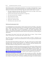
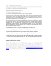
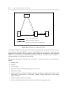
Selecting a Timing Source for the Switch
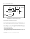
Before selecting a timing source, you should draw or obtain a copy of the network topology (which
indicates each node and the interconnecting digital trunk facilities). The nodes in the private network
should be stratified (divided) into two levels known as externally referenced and internally referenced
(sometimes called unreferenced). Externally referenced nodes are those within the private network that
connect directly to public network timing sources. Internally referenced nodes have digital facilities that do
not connect directly to public network timing sources. Figure B-11, External and Internal Reference
Levels, shows a typical network topology with externally and internally referenced nodes.