


MULTIPLEXED COMMUNICATION 1-29
_ ______________________________________________________________________________________
_ ______________________________________________________________________________________
_ ______________________________________________________________________________________
MULTIPLEXING OUTSIDE THE SWITCH
As signals propagate away from the switch, they can be multiplexed onto increasingly higher-capacity
facilities. As the capacity of facilities increases, the transmission medium can also change — for example,
from metallic to fiber to microwave and back again.
To understand multiplexing outside the switch, it may be helpful to study the process in the following
stages.
1. Multiplexing onto T1 trunks
2. Compressing the signal
3. Altering channel assignments on T1 trunks
4. Getting the signal ready for the central office
5. Changing the transmission medium from metallic to fiber-optic
6. Multiplexing with microwave
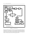
Each stage represents a multiplexing point, a transmission medium change point, or both. The sequence in
which the stages are shown approximates the order in which transformation or multiplexing can occur,
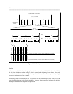
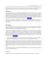
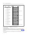
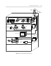
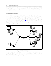
although this may vary among installations. (See figures 1-9 and 1-10 for some possible multiplexing
configurations.)
Regardless of the type of multiplexing and transmission media you choose to implement, however, when
you route transmissions through the network, always remember to maintain compatibility between both
ends of the connection. The options chosen on the originating DS1 port must agree with those set on the
destination port. In turn, the options chosen on intermediate multiplexers must generally agree with the
options chosen for the DS1 ports. One exception to this rule is the set of framing conventions for
intermediate multiplexers. With framing, the framing convention used at the origin and destination must
agree, but the framing used at intermediate multiplexers may differ from these endpoints. For example, if
bit multiplexing is used at the beginning of connection, bit demultiplexing must be used at the end of the
connection. If you select D4 framing for a trunk, you must set the receiving end for D4 framing, although
you may choose ESF framing for intermediate multiplexers (D4 to ESF to ESF to D4).
Multiplexing onto T1 Trunks
This stage in multiplexing occurs at the DS1 port on the System 75, System 85, and DEFINITY Generic 1
and Generic 2 communications systems. Depending upon how the DS1 port is administered, framing over
the T1 trunk may be D4 or ESF; signaling may be robbed-bit or 24th-channel; and the line coding may be
ZCS or B8ZS.
Multiplexing onto T1 trunks occurs at a D4 channel bank for the DIMENSION or for analog trunks on a
digital switch. Through byte interleaving, the D4 channel bank can multiplex signals for up to 48 analog
trunks onto two T1 trunks. T1 trunks originating at D4 channel banks have D4 framing with robbed-bit
signaling and ZCS line coding. Therefore, unless office channel unit (OCU) data-port cards are available
on the D4 unit, T1 lines originating at D4 channel banks are used to carry voice or voice-grade data only.
OCU data-port cards allow you to access AT&T’s DATAPHONE Digital Service (DDS) from a T1 trunk
originating at a D4 channel bank. With this capability, terminal devices, cluster controllers, and hosts