


SYNCHRONIZATION OF DIGITAL FACILITIES B-13
_ ______________________________________________________________________________________
_ ______________________________________________________________________________________
_ ______________________________________________________________________________________
The TN768 and TN780 circuit packs contain edge-mounted LEDs. These LEDs indicate the following
status sequences:
• Yellow LED is on 2.7 seconds and off 0.3 seconds — the tone-clock synchronizer is in ‘‘active’’ mode
and a DS1 is being used as a synchronization reference.
• Yellow LED is on 0.3 seconds and off 2.7 seconds — the tone-clock synchronizer is in ‘‘active’’ mode
and the local oscillator is being used as a synchronization reference.
• Yellow LED is on continuously — the tone-clock synchronizer reset properly but did not receive
translations update. It is in ‘‘active’’ mode and is providing synchronization from the local oscillator.
• Yellow LED is off continuously — the tone-clock synchronizer is in standby mode. It is neither
generating tones nor supplying a clock reference.
• The tone-clock synchronizer is characterized as being in either ‘‘active’’ mode (participating in the
synchronization process) or standby mode (not currently participating in the synchronization process).
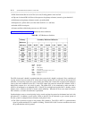
The best method to determine the mode of the tone-clock synchronization circuit pack is to execute the
system status command. While maintenance is running, both the yellow and green LEDs will
flash. The standby mode pattern is: on 0.1 seconds, off 0.2 seconds, on 0.1 seconds, off 0.4 seconds, on
0.4 seconds, off 0.4 seconds, repeatedly. The ‘‘active’’ mode pattern is different.
Criteria for Switching to the Secondary Reference
Each occurrence of an abnormal or error condition results in incrementing the appropriate error counter.
Each error counter has its own unique threshold limit. Exceeding an error counter’s threshold results in a
change in operation (such as switching to a different synchronization reference).
The principal error conditions used to determine if a change to a different clock synchronization reference
is needed are, in order of importance (items 2 through 6 apply only when the stratum-3 option is not used):
1. The master tone-clock synchronizer detects LOS.
2. The online reference reports a red alarm.
3. The online reference reports a blue alarm.
4. If more than 50% of those DS1 spans that are administered for slip-enable are experiencing slips
(with respect to the primary), then a decision is made to switch to the secondary.
5. The online reference reports that its misframe threshold has been exceeded.
6. The online reference reports that its slip threshold has been exceeded.
For switches that do not have the secondary reference, a switch to the local oscillator will only be made for
cases 1, 2, and 3.
Criteria for Switching Back to the Primary Reference
Each time the master tone-clock synchronizer reports a LOS, it increments the excessive reference switch
counter. If a total of 20 switches occur within a 1-hour interval then the local oscillator is placed online and
automatic reference switching is disabled. Automatic reference switching is only enabled by hourly
maintenance or by the enable synchronization command.