D-18 COMMUNICATIONS PROTOCOLS
_ ___________________________________________________________________________________________________________________________
_ ___________________________________________________________________________________________________________________________
_ ___________________________________________________________________________________________________________________________
_ ____________________________________________________
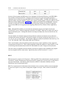
Transmit Pair 1&2 3&6
_ ____________________________________________________
Receive Pair 3&6 4&5
_ ____________________________________________________
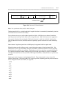
In terms of time sequence the DCP protocol was introduced with System 85 Release 1, the ISDN-BRI is
first available with System 85 R2V5. Therefore, the DCP protocol was the initial AT&T attempt to
implement what was then the unspecified ISDN basic rate interface (BRI). Like BRI, DCP supports two
separate 64-kbps voice/data channels (I-fields) and a separate signaling channel. However, there are several
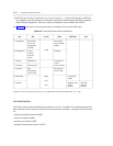
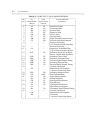
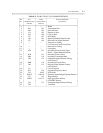
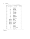
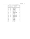
differences between BRI and DCP. Table D-5 is a comparison between DCP and ISDN-BRI. Note that
currently, and since the CCITT has not fully agreed on equivalent signaling for many DCP supported
services, those BRI services supported on the signaling channel are only a subset of those supported by
DCP.
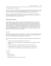
Note: Although DCP combines voice and data for transmission purposes, the digital switch routes
(switches) the voice (I1 channel) independent of the data (I2 channel). Both may be routed to the same or
separate destination ports. Although the channels can transport 64-kbps data, rates less than this are also
supported.
For data modules, the I-channel supports both asynchronous (character by character) and synchronous
(continuous bit stream) data formats. The protocol supports all common synchronous data rates (e.g., 1.2,
2.4, 4.8, 9.6, 19.2, 56, and 64 kbps). The I-channels support all common asynchronous data rates (e.g., 110;
134.5; 150; 300; 600; 1,200; 2,400; 4,800; 9,600; and 19,200 bps).
The S- and I-channels of the data modules provide all necessary control capabilities to fully support the
connected data terminal device. These control capabilities include the transport of control signals, as well
as initializing and maintenance data for RS-232C, RS-449/RS-423, and V.35 physical level protocols.
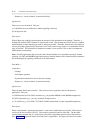
The wide variety of supported data rates and their associated or required control capabilities are grouped
into four categories known as data modes. Specifically, these are DATA modes 0, 1, 2, and 3.
BX.25
BX.25 protocol is a superset of X.25 protocol. AT&T uses BX.25 for communications over the System 85
and Generic 2 digital communications interface unit (DCIU) channel and over the System 75 and Generic 1
processor interface (PI). The following brief discussion of BX.25 is intended to introduce relevant
terminology used in describing the DCIU.
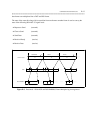
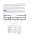
BX.25 is a layered protocol, which means that the details of error correction and flow control are handled
by lower level layers in a way which is transparent to higher level layers. Here are the levels the BX.25
uses:
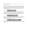
_ _________________________
Layer 5 Application Layer
_ _________________________
Layer 4 Session Layer
_ _________________________
Layer 3 Packet Layer
_ _________________________
Layer 2 Data-Link Layer
_ _________________________
Layer 1 Physical Layer
_ _________________________


