


B-20 SYNCHRONIZATION OF DIGITAL FACILITIES
_ ___________________________________________________________________________________________________________________________
_ ___________________________________________________________________________________________________________________________
_ ___________________________________________________________________________________________________________________________
If there are one or more clocks in the network at the lowest stratum level, the following steps can be taken
to determine the clock that should become the network reference clock source.
Step 1: If there is only one digital switch in the network, that switch is to be the network reference clock
master.
Step 2: If there is more than one digital switch in the network, rules 2 through 7 should be used to
determine the switch that should be the network reference clock (master).
Step 3: If there are no digital switches in the network, choose a digital terminal product as the network
reference clock master and have the other nodes derive timing from it. Listed in order of preference,
use a CEM, a D4-channel bank, or a CDM as the network reference clock master.
The CDMs can only be used to provide timing when they are used to emulate a D4-channel bank.
EXAMPLE FOR RULE 1
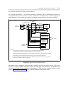
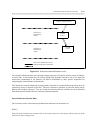
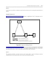
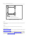
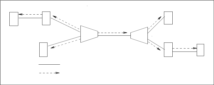
Figure B-12, Nonpublic Network without Digital Services, is used to explain the application of rule 1.
To determine the synchronization plan for figure B-12, Nonpublic Network without Digital Switches, the
following tasks were performed. First, according to rule 1, an attempt was made to find a node with the
lowest stratum clock. The attempt failed because all the nodes in the illustration provide stratum-4 timing.
Therefore, the steps under rule 1 must be used. Steps 1 and 2 are not applicable because there is no digital
switch in the network.
Under Step 3, it was determined, according to the ranking, that a CEM should be the network source clock.
Next, rules 2 through 7 were used to determine which of the two CEMs should be the network source clock.
For rules 2 through 6, both CEMs were equally qualified. Therefore, an arbitrary decision was made to
choose the CEM on the left.
D4D4
CEM
D4
D4
CEM
D4
D4
PRIMARY FREQUENCY REFERENCE
DIGITAL TRANSMISSION FACILITIES
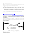
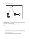
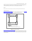
Figure B-12. Nonpublic Network without Digital Switches
The digital terminal products do not automatically switch to their internal high-accuracy clock on
synchronization reference failure.