


7-4 DATA CONNECTIVITY — AN OVERVIEW
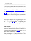
_ ___________________________________________________________________________________________________________________________
_ ___________________________________________________________________________________________________________________________
_ ___________________________________________________________________________________________________________________________
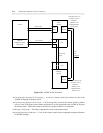
communications path.
• Interface protocols that control communication between links in a data network, but do not cross the
network. These protocols include the part of the RS-232 protocol that controls communication between
the originating DTE and DCE. Other examples, are the X.25 protocol, which is transformed as soon as
it enters the network, and the X.75 protocol.
Chapter 8 describes the DCEs that convert the transmission protocol as the signal enters and exits the
switch. In addition, it describes and explains how to use protocol converters, terminal emulation, and
gateway devices in the communications path between DTEs and networks using different protocols.
Refer to chapter 1, Introduction to Connectivity, and appendix D, Communications Protocols, for a
description of protocols and the role they play in communications through your communications system.
• Chapter 1 traces the conversion of protocols during data transmissions from transmission origination at
a DTE until transmission termination at the destination DTE.
• Appendix D lists various data communication protocols. Some protocols (for example, DMI and DCP)
relate to communication between DCEs; others (for example, BCS and SDLC) govern how the DTEs
package their data.
Analog vs. Digital
When speed is valued in a connection, digital facilities are always preferred because they can carry at
speeds up to 64 kbps. (With analog transmission, 9.6 kbps is the highest speed currently practical.) When
the connection is to an off-premises DTE, however, only analog facilities may be either economical or
available. In this case, as the signal enters or exits the switch, you use modem pooling to convert
transmissions between analog and digital. Chapter 8 describes and explains modem pooling configurations.
See chapter 1 for a discussion of the differences between analog and digital communications and the
implications each have in the transmission of data through the switch.
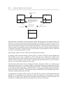
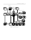
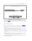
Synchronous vs. Asynchronous
Synchronous and asynchronous transmission (see figure 7-2) are named for whether all the bits in a
transmission arrive at a predetermined intervals — that is, whether the bits are synchronized with each
other.
In synchronous transmission, the DTE sends information in bursts of synchronized bits, one byte after
another. The originating DTE packages the bits into packets which conform to a layer 2 protocol (LAPD,
HDLC, and so forth) that the destination DTE understands. (See appendix D.)
With asynchronous transmission, however, the time between bursts of bits may be random. That is, in
asynchronous transmission, the DTE sends one group of bits (or burst) at a time, packaging them between
one or more start bits (to alert the destination DTE of incoming data and provide synchronization) and a
stop bit (to tell the destination DTE that transmission has ended).