


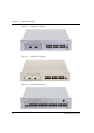
Chapter 2 P130 Front and Back Panels
Avaya P130 User’s Guide 13
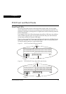
(*) This LED exists only in the P134G2
(**) Not activated for SFP Giga ports.
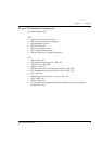
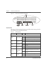
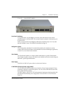
Avaya P130 Back Panel
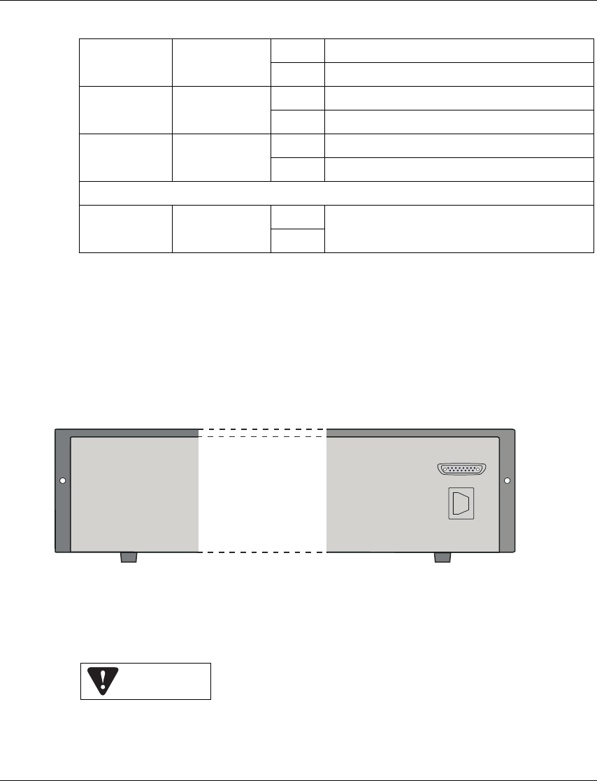
The Avaya P133G2 and P134G2 back panels have Power Supply and BUPS
connectors. Figure 2.4 shows the back panel of these switches.
Figure 2.4 P133G2/P134G2 AC Back Panels
BUPS Input Connector
The BUPS input connector (see Figure 2.4) is a 5 V DC connector for use with the
P130 BUPS unit only.
Rx (**) Rx traffic
On Packets received on this port
Off No activity on port
FDX
Full Duplex
Mode
On Port in Full Duplex mode
Off Port in Half Duplex mode
100M 100M Speed
On Port is working in 100M
Off Port is working in 10M or 1000M (Gig port)
Port-level
1...24
,51,52
LED per port
On
According to the function that was selected
from the function-level LEDs described above
Off
Table 2.1 LED Indications
Power Supply
Connector
BUPS
Connector
BUPS Input