


Chapter 4 Installation and Setup
24 Avaya P130 User’s Guide
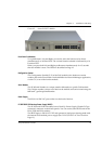
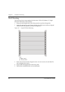
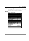
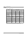
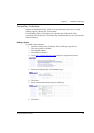
Figure 4.8 Incorrect Cable Connection
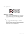
Powering On – P130 Module AC
For the AC input version of the P130, insert the power cord into the power inlet in
the back of the unit. The unit powers up.
1 If you are using a BUPS, insert a power cord from the BUPS into the BUPS
connector in the back of the unit. The unit powers up.
2 After power up or reset, the P130 performs a self test procedure.
Configuring the Switch
The P130 may be configured using the text-based Command Line Interface (CLI)
utility, the built-in P130 Device Manager (Embedded Web) or MultiService
Network Manager.
For instructions on the text-based utility, see the CLI chapter.
For instructions on installation of the graphical user interfaces, see the P130 Device
Manager Appendix. For instructions on the use of the graphical user interfaces,
refer to the Manager User’s Guide on the Management CD.
P130
EXPANSION
SLOT
51
FDX
15
52
COLLNK Tx Rx
1
13
51 52
23
14
8
20
5
17
100
4
16
6
18
7
19
10
22
9
21
OPRPW R
23
1112
24
13 14 15 16 17
1
LAG
234 5
CONSOLE
2118 19 20 2322 24
96
LAG
78 1110
LAG
12
P130
EXPANSION
SLOT
51
FDX
15
52
COLLNK Tx Rx
1
13
23
14
8
20
5
17
100
4
16
6
18
7
19
10
22
9
21
OPRPW R
23
1112
24
13 14 15 16 17
1
LAG
234 5
CONSOLE
2118 19 20 2322 24
96
LAG
78 1110
LAG
12
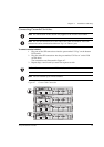
Down
Up
51 52
Down
Up