


Chapter 4 Installation and Setup
Avaya P130 User’s Guide 23
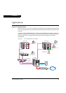
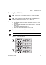
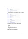
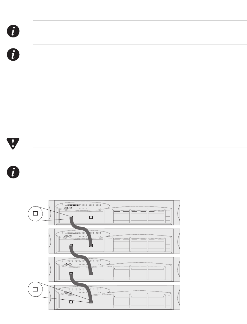
Connecting Cascaded Switches
Note: The information in this section only applies to the P133G2 and P134G2.
Note: The two SFP transceivers on the ends of the cable are identical. Each SFP
transceiver can be connected to either an “Up“ or “Down“ port.
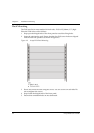
To connect cascaded switches
1 Plug one of the SFP transceivers into the port marked “52 Up” on the bottom
P130 switch.
2 Plug the other SFP transceiver into the port marked “51 Down” on the P130
switch above.
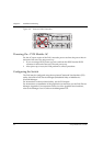
The connections are illustrated in Figure 4.7.
3 Repeat Steps 1 and 2 until you reach the topmost switch.
Caution: Do not cross connect two P130 switches with two cables.
Note: You can cascade up to 4 P130 switches.
Figure 4.7 Correct Cable Connection
P130
EXPANSION
SLOT
51
FDX
15
52
COLLNK Tx Rx
1
13
23
14
8
20
5
17
100
4
16
6
18
7
19
10
22
9
21
OPRPWR
23
1112
24
13 14 15 16 17
1
LAG
234 5
CONSOLE
2118 19 20 2322 24
9
6
LAG
78 1110
LAG
12
P130
EXPANSION
SLOT
51
FDX
15
52
COLLNK Tx Rx
1
13
23
14
8
20
5
17
100
4
16
6
18
7
19
10
22
9
21
OPRPWR
23
1112
24
13 14 15 16 17
1
LAG
234 5
CONSOLE
2118 19 20 2322 24
9
6
LAG
78 1110
LAG
12
P130
EXPANSION
SLOT
51
FDX
15
52
COLLNK Tx Rx
1
13
23
14
8
20
5
17
100
4
16
6
18
7
19
10
22
9
21
OPRPWR
23
1112
24
13 14 15 16 17
1
LAG
234 5
CONSOLE
2118 19 20 2322 24
96
LAG
78 1110
LAG
12
P130
EXPANSION
SLOT
51
FDX
15
52
COLLNK Tx Rx
1
13
23
14
8
20
5
17
100
4
16
6
18
7
19
10
22
9
21
OPRPWR
23
1112
24
13 14 15 16 17
1
LAG
234 5
CONSOLE
2118 19 20 2322 24
96
LAG
78 1110
LAG
12
51 52
Down
Up
51 52
Down
Up
51 52
Down
Up
51 52
Down
Up
52
51
UP
Down