


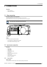
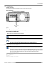
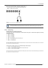

3. Connections
Inputs
R
G
B H V
VIDEO
RGBHV
R
G
B H V
-
RG
S
B
R
G
S
B
- - -
RGBS
R
G
B
S
- -
Component
PR Y PB
- - -
S-Video
- - - -
C
Y
S-Video C
-
Y
- - -
Composite VIDEO
- - - - -
Composite
-
VIDEO
- - - -
Composite
- -
VIDEO
- - -
Composite
- - - -
VIDEO
Signals
Composite
- - - - -
VIDEO
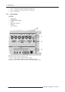
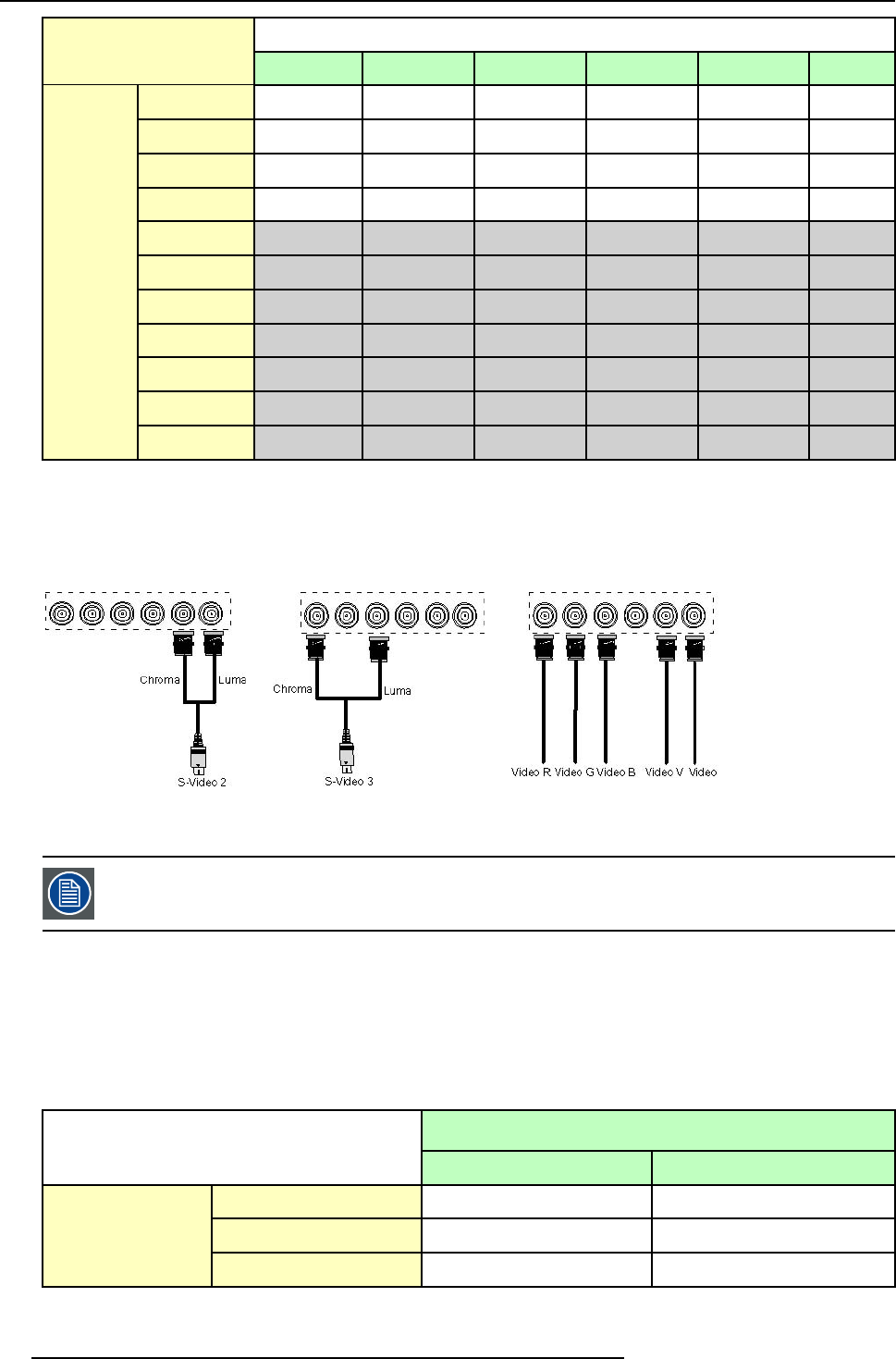
Table 3-2
Extended configuration of the 5 cable input: the first column gives the possible signals, and the first row the 5 cable input connectors(+ the standard Video BNC).
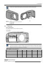
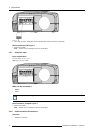
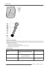
How to set up the 5 cable extended configuration ?
1. Connect the video or S-video source to the desired BNC connector
Note: In some cases an adapter ca ble is required (image 3-10, image 3-11, image 3-12)
Image 3-10
Connecting an S-Video signal on the Vs
&
Video BNC
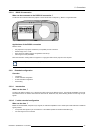
Image 3-11
Connecting an S-Video signal on the R & B
BNC
Image 3-12
Connecting composite Video signals on the
5 cable input
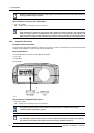
Multiple video signals can not be visualized simultaneously since there isonly one decoder. However, the use
of the optional Audio & video layer(3) allows to visualize up to 2 different video signals (in PiP mode ).
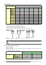
3.2.9.3 S-Video extended configuration
What can be done ?
Beside the standard luminance (Y) and chrominance (C) signals, the advanced capabilities of the S-Video input make treatment of
additional signals possible:
• 2 composite video signal may be connected.
Inputs
Y
C
S-Video
Y
C
Composite Video
Video
-
Signals
Composite Video
-
Video
Table 3-3
Extended configuration of the S-Video input: the first column gives the possible signals, and the first row the S-Video inputs pins.
26 R5976694 IQ PRO R500 01/02/2007