


2-4
Installation Guidelines
5976135 BARCOSIM 6 21032000
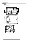
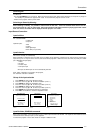
Lens formulas to calculate the projector distance.
Metric formulas (meter) Inch formulas (inch)
QGD(1.36-2:1) PD
min
=1.371 x SW + 0.165 + 0.0083/SW PD
min
=1.371 x SW + 6.5 + 12.86/SW
PD
max
=2.086 x SW + 0.153 - 0.015/SW PD
max
=2.086 x SW + 6.02 - 23.25/SW
QGD(7:1) PD = 7.021 x SW + 0.047 + 0.0093/SW PD
= 7.021 x SW + 1.85 + 14.41/SW
QGD(0.8:1) PD = 0.794 x SW - 0.048 + 0.0072/SW PD = 0.794 x SW - 1.89 + 11.16/SW
QDG(1.27:1) PD = 1.356 x SW - 0.065 + 0.0297/SW PD
= 1.356 x SW - 2.56 + 46.03/SW
QGD(2-2.8) PD
min
= 1.982 x SW + 0.476 - 0.388/SW PD
min
= 1.982 x SW + 18.74 - 601.4/SW
PD
max
= 2.778 x SW + 0.068 - 0.015/SW PD
max
= 2.778 x SW + 2.68 - 23.25/SW
QFD(1.27:1) PD = 1.33 x SW - 0.0195 + 0.0270/SW PD
= 1.33 x SW - 0.77 + 41.85/SW
QFD(1.4-2:1) PD
min
= 1.48 x SW - 0.0287 - 0.0215/SW PD
min
= 1.48 x SW - 1.30 - 33.32/SW
PD
max
= 2.25 x SW - 0.01 + 0.0195/SW PD
max
= 2.25 x SW - 0.39 + 30.22/SW
QFD(2.1-3:1) PD
min
= 2.18 x SW - 0.1 + 0.055/SW PD
min
= 1.48 x SW - 3.94 + 85.25/SW
PD
max
= 2.97 x SW + 0.1 - 0.073/SW PD
max
= 2.25 x SW + 3.94 - 113.15/SW
QFD (2.5:1) PD = 2.486 x SW + 0.025 + 0.0215/SW PD = 2.486 x SW + 0.98 + 33.32/SW
QFD(4.5-6:1) PD
min
= 4.39 x SW - 0.02 - 0.029/SW PD
min
= 4.39 x SW - 0.79 - 44.95/SW
PD
max
= 6.00 x SW + 0.15 - 0.107/SW PD
max
= 6.00 x SW + 5.91 - 185.65/SW
Lens program to calculate the projector distance is available on the BARCO webside :
http://www.barco.com/projecti/cusserv/index.htm
Remark :
In case of the Scheimpflug version lens, the formulas are valid in the normal position.
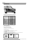
How to install the lens?
Installation of the lens for a standard SIM projector.
The installation of the scheimphlug lens is described in the corresponding lens kit.
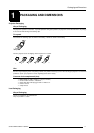
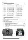
1. Take the lens out of its packing material.
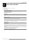
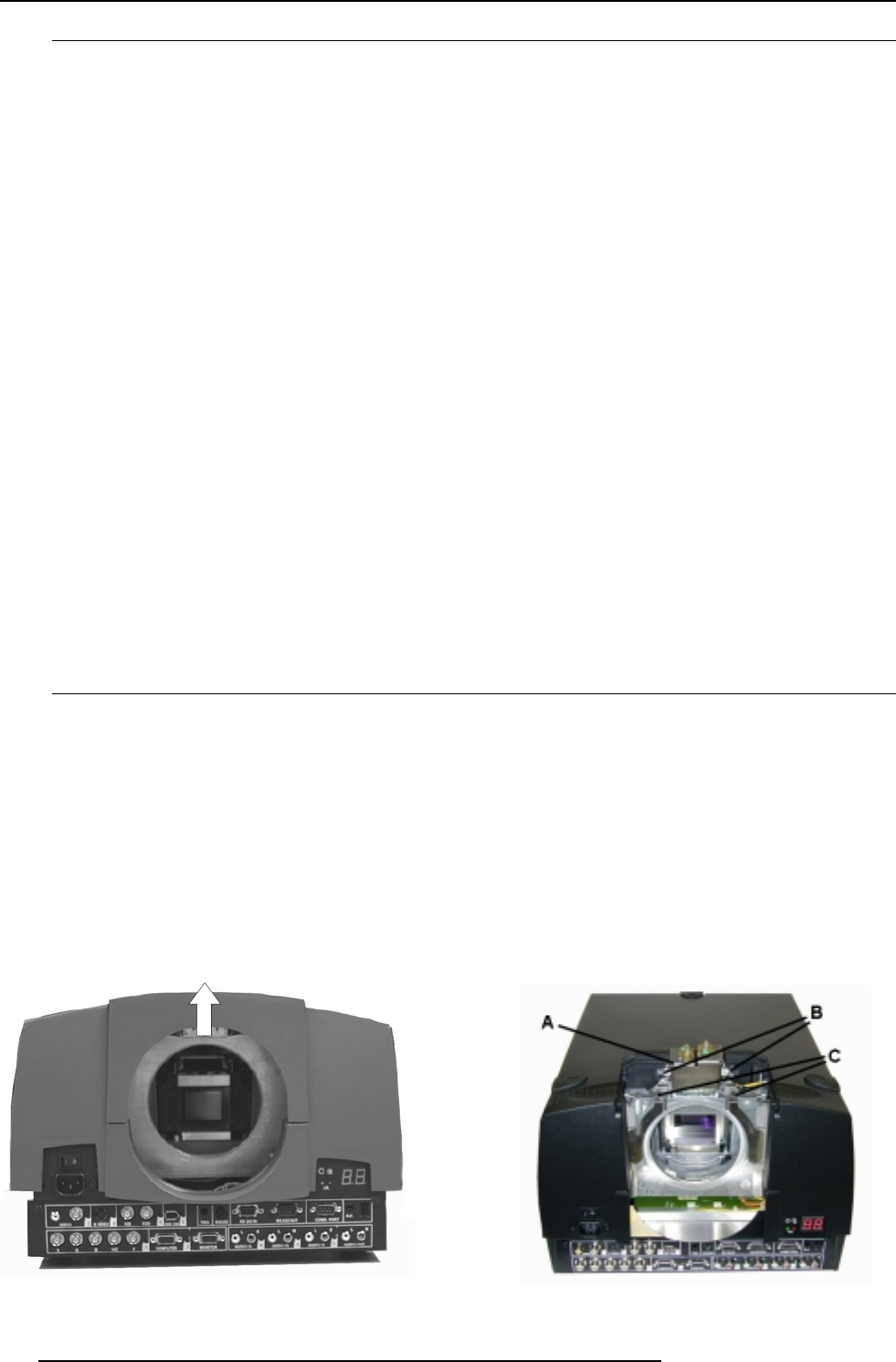
2. Open the lens cover of the projector by pivoting it up and take it off. image 1
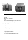
3. Loosen the fixing screws (B) of the motor part (A) and flip the motor part up. image 2
4. Open both lens locks (C) by pulling them backwards (first, lift up a little before pulling backwards). image 2
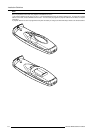
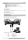
5. Put the lens on the lens holder.
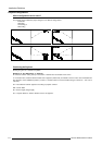
6. Fix the lens by closing the both locks (C) until they are secured. image 3
7. Flip the motor part back (A) (if a motorized lens is installed, be sure the teeth match the tooth profile (D) of the lens)
and secure with the fixing screws (B). image 3
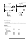
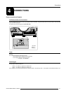
8. Re-install the lens cover. image 4
Image 1
Image 2