


104
SERVSWITCH™ AND SERVSWITCH ULTRA™
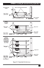
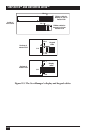
14. Mount the two washers included with the Overlay Option Board on the two
screws that are also included. (You might have removed these from the
Board’s mounting standoffs in Step 12.) Screw the screws through the bottom
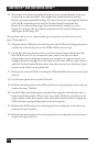
of the PCB’s mounting holes into the Overlay Board’s standoffs. See
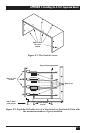
Figure E-2 on the previous page. For mini ServSwitch models, see also
Figure E-1 on page 101; for other ServSwitch models and ServManagers, see
also Figure E-4 on page 107.
(If your Serv unit is a 2- or 4-port model, go to step 20—you don’t have to do
steps 15 through 19.)
15. Plug the master PCB back into the bottom of the PCB stack, being extremely
careful not to bend the pins on the PCB-to-PCB connector J3.
16. Check the clearance between the top of the Overlay Option Board and the
slave PCB above it. If any component pins (that is, the pins by which
components such as chips and resistors are attached to a circuit board) are
hanging down far enough from the bottom of the slave PCB to make contact
with the Overlay Option Board, either bend them away from the Board (and
not into each other) or snip them off.
17. Refasten the master PCB by screwing the PCB standoffs you removed in step 9
back in.
18. Put the back panel back on the PCB stack.
19. Refasten the back panel to the PCB stack by screwing the jack screws that you
removed in step 7 back in.
20. Put the PCB(s)-plus-back-panel assembly back together with the Serv unit’s
bottom and front panels. (This can be very tricky. Hold the assembly at a 45˚
angle relative to the front panel—this will make it much easier to realign the
LEDs with the corresponding holes in the front panel.)
21. Refasten the PCB stack to the bottom panel by screwing the screws that you
removed in step 5 back in.
22. Refasten the back panel to the bottom panel by screwing the screws that you
removed in step 4 back in.