


114
SERVSWITCH™ AND SERVSWITCH ULTRA™
15. Put the PCB-stack-plus-back-panel assembly back together with the Switch’s
bottom and front panels. (This can be very tricky. Hold the assembly at a 45˚
angle relative to the front panel—this will make it much easier to realign the
LEDs with the corresponding holes in the front panel.)
16. Refasten the PCB stack to the bottom panel by screwing the screws that you
removed in step 5 back in.
17. Refasten the back panel to the bottom panel by screwing the screws that you
removed in step 4 back in.
Before putting the Switch’s top cover back on, test the unit as directed in steps 18
through 22.
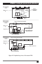
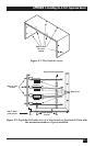
18. Temporarily connect the Switch to a monitor, keyboard, and mouse, along
with at least one CPU for every PCB in the Switch. (On a Switch you have just
expanded to twelve ports, for example, one CPU should be attached to port 1,
one CPU to port 5, and one CPU to port 9.)
19. Plug the Switch back in and turn it ON. (If, using the configuration currently
stored in its NVRAM, the Switch won’t be able to switch to all of the test
CPUs, you might have to change the Switch’s Maximum Ports, Width, and
Units values, or just perform a factory reset. Refer to Sections 4.3.8 through
4.3.10 or Section 6.1.)
20. Turn ON the attached monitor and CPUs.
21. Make sure that the Switch’s front-panel pushbuttons, keyboard commands,
and overlay menus will still scan and switch between all of the CPUs from the
front panel as before. If the Switch does not respond properly, call Black Box
for technical support.
22. If the Switch seems to be working properly, turn OFF the Switch and all
attached test equipment. Unplug the Switch from utility power and
disconnect it from the test equipment.
23. Replace the Switch’s top cover.
24. Refasten the top cover by screwing the screws that you removed in step 2 back
in.