


111
APPENDIX F: Installing the 4-Port Expansion Board
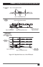
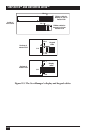
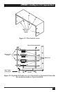
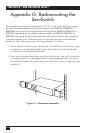
Figure F-1. The Switch’s cover.
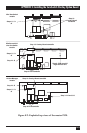
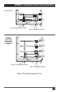
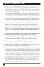
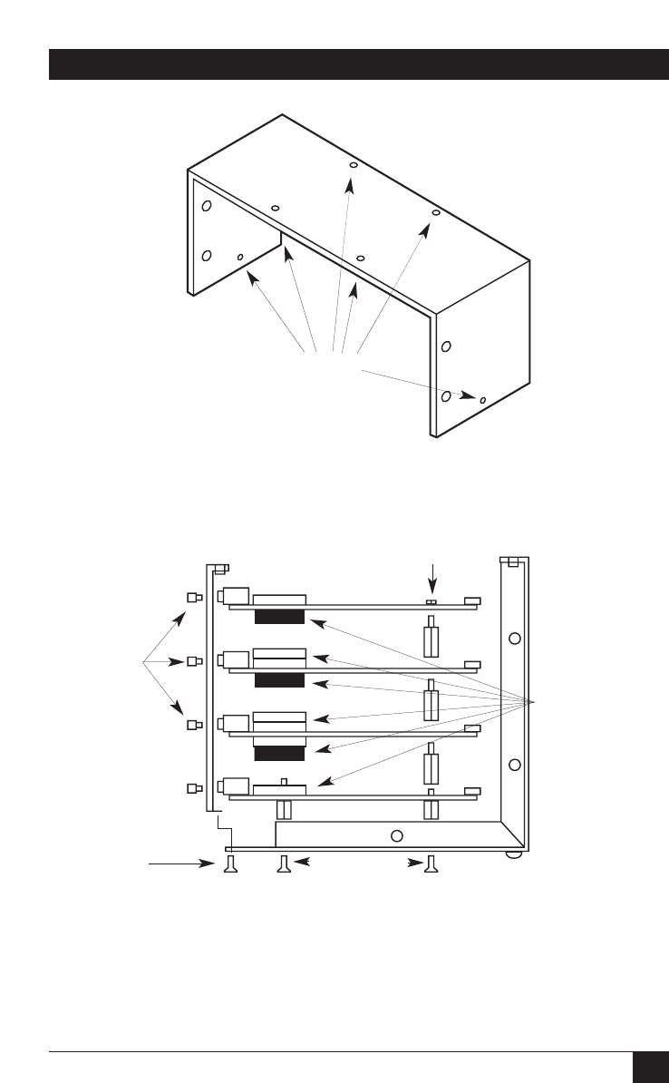
Figure F-2. Exploded left-side view of a ServSwitch or ServSwitch Ultra with
the maximum number of ports installed.
Step 2: Holes
for cover
screws
Step 4: Back-
plate screws
Step 13: Jack
screws
Step 5: Bottom
screws
Step 10: J3
Step 8: Nuts and washers