


112
SERVSWITCH™ AND SERVSWITCH ULTRA™
8. Unscrew and remove the nuts and washers from the screw-ends of the
standoffs that poke through the topmost PCB. There will definitely be two of
these standoffs at the front of the PCB; there might also be one on the narrow
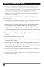
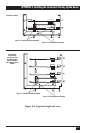
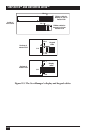
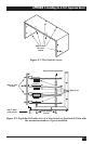
right-hand end. See Figure F-2 on the previous page, Figure F-4 on the next
page, and Figure F-5 on page 115.
4-port models (single PCB): These standoffs will be the short, jack-screw-
like affairs that serve to separate the board from the bottom panel. Also, do
not remove the screws or standoffs that attach the overlay board to the PCB.
9. Unscrew and remove the eight jack screws attached. to the Expansion Board,
one on either side of the Board’s four DB25 connectors. (These will secure
the connectors to the backplate; you will be screwing them back on soon.)
10. You should have received two or three new standoffs with your Expansion
Board. Screw these into the screw-ends of the existing standoffs that you
exposed in step 8. You should also have received an extender (spacer) for the
J3 connector on the PCB that will be below the Expansion Board (see
Figure F-2 on the previous page, Figure F-4 on the next page, and Figure F-5
on page 115); plug this extender into the J3 connector, being careful not to
bend the extender’s pins.
11. Plug the 4-Port Expansion Board into the J3 extender you just attached, being
extremely careful not to bend the Board’s pins (see Figure F-2 on the
previous page and Figure F-5 on page 115). The new standoffs’ screw-ends
should poke through the appropriate holes on the Board, and the Board’s
DB25 connectors should fit in the CPU-port slots you exposed in step 7.
12. Fasten the Board to the other PCB(s) by screwing the nuts and washers you
removed in step 8 onto the screw-ends of the new standoffs.
13. Fasten the Board to the back panel by screwing the jack screws you removed
in step 9 back in. (See Figure F-2 on the previous page.)
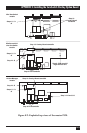
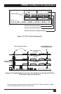
14. Make sure that port-numbering jumper J14 (see Figure F-4 on the next page
and Figure F-5 on page 115) is set correctly on all of your unit’s “slave boards”
(all the boards in the PCB stack except the bottommost main board). On the
second board from the bottom, J14 should be removed to identify that board as
the location of ports 5 through 8. On the third board from the bottom (if
you’ve installed one), J14 should be set to the left to identify that board as the
location of ports 9 through 12. On the fourth board (again, if you’ve installed
one), J14 should be set to the right to identify that board as the location of
ports 13 through 16. If these jumpers aren’t set correctly, the Switch will
either access the wrong ports, access multiple ports simultaneously, or light
LED 3 (“slave-communication error”) at power-up.