


113
APPENDIX F: Installing the 4-Port Expansion Board
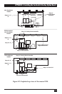
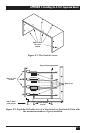
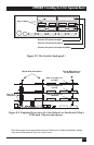
Figure F-3. The Switch’s back panel*.
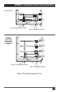
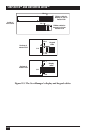
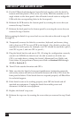
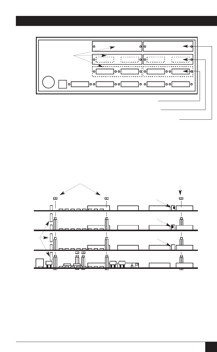
Figure F-4. Exploded front view of a ServSwitch’s or ServSwitch Ultra’s
PCB stack (16-port unit shown).
*Solid lines show actual appearance of 8-port Switch prior to Board installation; dotted
lines show differences for 4-port or 12-port units.
Step 7: Blanks
Slots for CPU ports 5 through 8
Slots for CPU ports 9 through 12
Slots for CPU ports 13 through 16 (hidden)
Step 8: Nuts and washers
Step 14: Jumper J14
(on right)
Step 8: Might also be a
nut and washer here
Step 14: Jumper J14
(on left)
Step 14: Jumper J14
(removed)
Step 10: J3
extenders