


Section 2: Source Setup
RPMX/CX50/CX60/CX67 User’s Manual 2-5
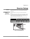
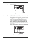
Figure 2.8. S-Video Loop Through
There are two, 9-pin DIN connectors on the input panel dedicated to serial
communication. These connectors allow you to connect your projector to an
external controlling device with a serial interface, such as a personal computer,
for the purpose of communicating without having to use the keypad.
SINGLE PROJECTOR
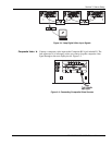
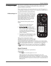
Connection: Using the appropriate serial communication cable (see Appendix
D), connect the controlling device (PC) to the serial port labeled RS-232 IN.
(Figure 2.9.)
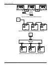
Figure 2.9. Single Projector Connection and Communication Schematic
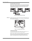
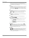
MULTIPLE PROJECTORS
Connection: When connecting multiple projectors in a network, use an
appropriate serial communication cable (Appendix D) and connect the controlling
device (PC) to the RS-232 IN connector of the first projector in the network.
With a second serial communication cable, connect the one end to the RS-232
OUT connector of the first projector and the other end to the RS-232 IN of the
next projector. Continue this pattern of connection with all projectors (Figure
2.10.). The last projector in the network will only have a connection to the RS-
232 IN connector. Then set the baud rate of all projectors to match that of the
controlling device. Refer to Communication on page 3-19 for details on setting
baud rate.
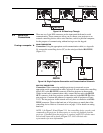
NOTE: 1) In Figure 2.10 and Figure 2.11, the controlling device can only send
commands to the projector. It cannot query or receive any feedback from the
projector. If feedback from the projector is required, an RS-232 switcher must
be used and connected as shown in Figure 2.12. Call a Christie sales
representative for more information.
2.2 Serial Port
Connections
If usin
g
a com
p
uter '