


42-7
Catalyst 3750-E and 3560-E Switch Software Configuration Guide
OL-9775-02
Chapter 42 Configuring IP Multicast Routing
Understanding Cisco’s Implementation of IP Multicast Routing
Bootstrap Router
PIMv2 BSR is another method to distribute group-to-RP mapping information to all PIM routers and
multilayer switches in the network. It eliminates the need to manually configure RP information in every
router and switch in the network. However, instead of using IP multicast to distribute group-to-RP
mapping information, BSR uses hop-by-hop flooding of special BSR messages to distribute the mapping
information.
The BSR is elected from a set of candidate routers and switches in the domain that have been configured
to function as BSRs. The election mechanism is similar to the root-bridge election mechanism used in
bridged LANs. The BSR election is based on the BSR priority of the device contained in the BSR
messages that are sent hop-by-hop through the network. Each BSR device examines the message and
forwards out all interfaces only the message that has either a higher BSR priority than its BSR priority
or the same BSR priority, but with a higher BSR IP address. Using this method, the BSR is elected.
The elected BSR sends BSR messages with a TTL of 1. Neighboring PIMv2 routers or multilayer
switches receive the BSR message and multicast it out all other interfaces (except the one on which it
was received) with a TTL of 1. In this way, BSR messages travel hop-by-hop throughout the PIM
domain. Because BSR messages contain the IP address of the current BSR, the flooding mechanism
enables candidate RPs to automatically learn which device is the elected BSR.
Candidate RPs send candidate RP advertisements showing the group range for which they are
responsible to the BSR, which stores this information in its local candidate-RP cache. The BSR
periodically advertises the contents of this cache in BSR messages to all other PIM devices in the
domain. These messages travel hop-by-hop through the network to all routers and switches, which store
the RP information in the BSR message in their local RP cache. The routers and switches select the same
RP for a given group because they all use a common RP hashing algorithm.
Multicast Forwarding and Reverse Path Check
With unicast routing, routers and multilayer switches forward traffic through the network along a single
path from the source to the destination host whose IP address appears in the destination address field of
the IP packet. Each router and switch along the way makes a unicast forwarding decision, using the
destination IP address in the packet, by looking up the destination address in the unicast routing table
and forwarding the packet through the specified interface to the next hop toward the destination.
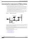
With multicasting, the source is sending traffic to an arbitrary group of hosts represented by a multicast
group address in the destination address field of the IP packet. To decide whether to forward or drop an
incoming multicast packet, the router or multilayer switch uses a reverse path forwarding (RPF) check
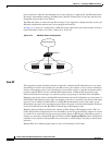
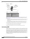
on the packet as follows and shown in Figure 42-3:
1. The router or multilayer switch examines the source address of the arriving multicast packet to
decide whether the packet arrived on an interface that is on the reverse path back to the source.
2. If the packet arrives on the interface leading back to the source, the RPF check is successful and the
packet is forwarded to all interfaces in the outgoing interface list (which might not be all interfaces
on the router).
3. If the RPF check fails, the packet is discarded.
Some multicast routing protocols, such as DVMRP, maintain a separate multicast routing table and use
it for the RPF check. However, PIM uses the unicast routing table to perform the RPF check.
Figure 42-3 shows port 2 receiving a multicast packet from source 151.10.3.21. Table 42-1 shows that
the port on the reverse path to the source is port 1, not port 2. Because the RPF check fails, the multilayer
switch discards the packet. Another multicast packet from source 151.10.3.21 is received on port 1, and
the routing table shows this port is on the reverse path to the source. Because the RPF check passes, the
switch forwards the packet to all port in the outgoing port list.