


40-3
Catalyst 3750-E and 3560-E Switch Software Configuration Guide
OL-9775-02
Chapter 40 Configuring HSRP and Enhanced Object Tracking
Understanding HSRP
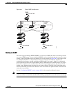
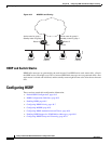
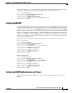
Figure 40-1 Typical HSRP Configuration
Multiple HSRP
The switch supports Multiple HSRP (MHSRP), an extension of HSRP that allows load sharing between
two or more HSRP groups. You can configure MHSRP to achieve load-balancing and to use two or more
standby groups (and paths) from a host network to a server network. In Figure 40-2, half of the clients
are configured for Router A, and half of the clients are configured for Router B. Together, the
configuration for Routers A and B establish two HSRP groups. For group 1, Router A is the default
active router because it has the assigned highest priority, and Router B is the standby router. For group 2,
Router B is the default active router because it has the assigned highest priority, and Router A is the
standby router. During normal operation, the two routers share the IP traffic load. When either router
becomes unavailable, the other router becomes active and assumes the packet-transfer functions of the
router that is unavailable.
See the “Configuring MHSRP” section on page 40-9 for the example configuration steps.
Note For MHSRP, you need to enter the standby preempt interface configuration command on the HSRP
interfaces so that if a router fails and then comes back up, preemption occurs and restores load sharing
Host B
172.20.130.5
172.20.128.32
Host A
172.20.128.55
172.20.128.1 172.20.128.3 172.20.128.2
Virtual
router
Active
router
Standby
router
Router A Router B
101361
Host C