


11-11
Catalyst 3750-E and 3560-E Switch Software Configuration Guide
OL-9775-02
Chapter 11 Configuring Interface Characteristics
Understanding Interface Types
Because the switch supports internal power supplies and the Cisco Redundant Power System 2300 (also
referred to as the RPS 2300), the total amount of power available for the powered devices varies
depending on the power supply configuration.
• If a power supply is removed and replaced by a new power supply with less power and the switch
does not have enough power for the powered devices, the switch denies power to the PoE ports in
auto mode in descending order of the port numbers. If the switch still does not have enough power,
the switch then denies power to the PoE ports in static mode in descending order of the port
numbers.
• If the new power supply supports more power than the previous one and the switch now has more
power available, the switch grants power to the PoE ports in static mode in ascending order of the
port numbers. If it still has power available, the switch then grants power to the PoE ports in auto
mode in ascending order of the port numbers.
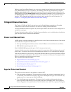
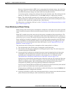
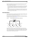
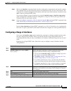
Connecting Interfaces
Devices within a single VLAN can communicate directly through any switch. Ports in different VLANs
cannot exchange data without going through a routing device. With a standard Layer 2 switch, ports in
different VLANs have to exchange information through a router.
By using the switch with routing enabled, when you configure both VLAN 20 and VLAN 30 with an
SVI to which an IP address is assigned, packets can be sent from Host A to Host B directly through the
switch with no need for an external router (Figure 11-1).
Figure 11-1 Connecting VLANs with the Catalyst 3750-E or 3560-E Switch
When the IP services feature set is running on the switch or the stack master, the switch uses two
methods to forward traffic between interfaces: routing and fallback bridging. If the IP base feature set
is on the switch or the stack master, only basic routing (static routing and RIP) is supported. Whenever
possible, to maintain high performance, forwarding is done by the switch hardware. However, only IPv4
packets with Ethernet II encapsulation are routed in hardware. Non-IP traffic and traffic with other
encapsulation methods are fallback-bridged by hardware.
Host A
SVI 1172.20.128.1 172.20.129.1SVI 2
Layer 3 switch
with routing enabled
VLAN 20
Host B
VLAN 30
101350