


6-2
Catalyst 3750-E and 3560-E Switch Software Configuration Guide
OL-9775-02
Chapter 6 Clustering Switches
Understanding Switch Clusters
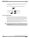
In a switch cluster, 1 switch must be the cluster command switch and up to 15 other switches can be
cluster member switches. The total number of switches in a cluster cannot exceed 16 switches. The
cluster command switch is the single point of access used to configure, manage, and monitor the cluster
member switches. Cluster members can belong to only one cluster at a time.
Note A switch cluster is different from a switch stack. A switch stack is a set of Catalyst 3750-E and 3750
switches connected through their stack ports. For more information about how switch stacks differ from
switch clusters, see the “Switch Clusters and Switch Stacks” section on page 6-16.
The benefits of clustering switches include:
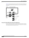
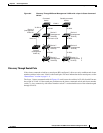
• Management of Catalyst switches regardless of their interconnection media and their physical
locations. The switches can be in the same location, or they can be distributed across a Layer 2 or
Layer 3 (if your cluster is using a Catalyst 3560, Catalyst 3750, Catalyst 3560-E, or Catalyst 3750-E
switch as a Layer 3 router between the Layer 2 switches in the cluster) network.
Cluster members are connected to the cluster command switch according to the connectivity
guidelines described in the “Automatic Discovery of Cluster Candidates and Members” section on
page 6-5. This section includes management VLAN considerations for the Catalyst 1900,
Catalyst 2820, Catalyst 2900 XL, Catalyst 2950, and Catalyst 3500 XL switches. For complete
information about these switches in a switch-cluster environment, see the software configuration
guide for that specific switch.
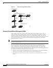
• Command-switch redundancy if a cluster command switch fails. One or more switches can be
designated as standby cluster command switches to avoid loss of contact with cluster members. A
cluster standby group is a group of standby cluster command switches.
• Management of a variety of Catalyst switches through a single IP address. This conserves on IP
addresses, especially if you have a limited number of them. All communication with the switch
cluster is through the cluster command switch IP address.
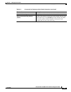
Table 6-1 lists the Catalyst switches eligible for switch clustering, including which ones can be cluster
command switches and which ones can only be cluster member switches, and the required software
versions.
Table 6-1 Switch Software and Cluster Capability
Switch Cisco IOS Release Cluster Capability
Catalyst 3750-E 12.2(35)SE2 or later Member or command switch
Catalyst 3750 12.1(11)AX or later Member or command switch
Catalyst 3560-E 12.2(35)SE2 or later Member or command switch
Catalyst 3560 12.1(19)EA1b or later Member or command switch
Catalyst 3550 12.1(4)EA1 or later Member or command switch
Catalyst 2970 12.1(11)AX or later Member or command switch
Catalyst 2960 12.2(25)FX or later Member or command switch
Catalyst 2955 12.1(12c)EA1 or later Member or command switch
Catalyst 2950 12.0(5.2)WC(1) or later Member or command switch
Catalyst 2950 LRE 12.1(11)JY or later Member or command switch
Catalyst 2940 12.1(13)AY or later Member or command switch
Catalyst 3500 XL 12.0(5.1)XU or later Member or command switch