


18-10
Catalyst 3750-E and 3560-E Switch Software Configuration Guide
OL-9775-02
Chapter 18 Configuring STP
Understanding Spanning-Tree Features
Because each VLAN is a separate spanning-tree instance, the switch accelerates aging on a per-VLAN
basis. A spanning-tree reconfiguration on one VLAN can cause the dynamic addresses learned on that
VLAN to be subject to accelerated aging. Dynamic addresses on other VLANs can be unaffected and
remain subject to the aging interval entered for the switch.
Spanning-Tree Modes and Protocols
The switch supports these spanning-tree modes and protocols:
• PVST+—This spanning-tree mode is based on the IEEE 802.1D standard and Cisco proprietary
extensions. It is the default spanning-tree mode used on all Ethernet port-based VLANs. The PVST+
runs on each VLAN on the switch up to the maximum supported, ensuring that each has a loop-free
path through the network.
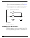
The PVST+ provides Layer 2 load-balancing for the VLAN on which it runs. You can create
different logical topologies by using the VLANs on your network to ensure that all of your links are
used but that no one link is oversubscribed. Each instance of PVST+ on a VLAN has a single root
switch. This root switch propagates the spanning-tree information associated with that VLAN to all
other switches in the network. Because each switch has the same information about the network, this
process ensures that the network topology is maintained.
• Rapid PVST+—This spanning-tree mode is the same as PVST+ except that is uses a rapid
convergence based on the IEEE 802.1w standard. To provide rapid convergence, the rapid PVST+
immediately deletes dynamically learned MAC address entries on a per-port basis upon receiving a
topology change. By contrast, PVST+ uses a short aging time for dynamically learned MAC address
entries.
The rapid PVST+ uses the same configuration as PVST+ (except where noted), and the switch needs
only minimal extra configuration. The benefit of rapid PVST+ is that you can migrate a large PVST+
install base to rapid PVST+ without having to learn the complexities of the MSTP configuration and
without having to reprovision your network. In rapid-PVST+ mode, each VLAN runs its own
spanning-tree instance up to the maximum supported.
• MSTP—This spanning-tree mode is based on the IEEE 802.1s standard. You can map multiple
VLANs to the same spanning-tree instance, which reduces the number of spanning-tree instances
required to support a large number of VLANs. The MSTP runs on top of the RSTP (based on
IEEE 802.1w), which provides for rapid convergence of the spanning tree by eliminating the
forward delay and by quickly transitioning root ports and designated ports to the forwarding state.
In a switch stack, the cross-stack rapid transition (CSRT) feature performs the same function as
RSTP. You cannot run MSTP without RSTP or CSRT.
The most common initial deployment of MSTP is in the backbone and distribution layers of a
Layer 2 switched network. For more information, see Chapter 19, “Configuring MSTP.”
For information about the number of supported spanning-tree instances, see the next section.
Supported Spanning-Tree Instances
In PVST+ or rapid-PVST+ mode, the switch or switch stack supports up to 128 spanning-tree instances.
In MSTP mode, the switch or switch stack supports up to 65 MST instances. The number of VLANs that
can be mapped to a particular MST instance is unlimited.
For information about how spanning tree interoperates with the VLAN Trunking Protocol (VTP), see
the “Spanning-Tree Configuration Guidelines” section on page 18-13.