


11-5
Catalyst 3750-E and 3560-E Switch Software Configuration Guide
OL-9775-02
Chapter 11 Configuring Interface Characteristics
Understanding Interface Types
Switch Virtual Interfaces
A switch virtual interface (SVI) represents a VLAN of switch ports as one interface to the routing or
bridging function in the system. Only one SVI can be associated with a VLAN, but you need to configure
an SVI for a VLAN only when you wish to route between VLANs, to fallback-bridge nonroutable
protocols between VLANs, or to provide IP host connectivity to the switch. By default, an SVI is created
for the default VLAN (VLAN 1) to permit remote switch administration. Additional SVIs must be
explicitly configured.
Note You cannot delete interface VLAN 1.
SVIs provide IP host connectivity only to the system; in Layer 3 mode, you can configure routing across
SVIs.
Although the switch stack or switch supports a total of 1005 VLANs (and SVIs), the interrelationship
between the number of SVIs and routed ports and the number of other features being configured might
impact CPU performance because of hardware limitations. See the “Configuring Layer 3 Interfaces”
section on page 11-31 for information about what happens when hardware resource limitations are
reached.
SVIs are created the first time that you enter the vlan interface configuration command for a VLAN
interface. The VLAN corresponds to the VLAN tag associated with data frames on an ISL or
IEEE 802.1Q encapsulated trunk or the VLAN ID configured for an access port. Configure a VLAN
interface for each VLAN for which you want to route traffic, and assign it an IP address. For more
information, see the “Manually Assigning IP Information” section on page 3-10.
Note When you create an SVI, it does not become active until it is associated with a physical port.
SVIs support routing protocols and bridging configurations. For more information about configuring IP
routing, see Chapter 38, “Configuring IP Unicast Routing,” Chapter 42, “Configuring IP Multicast
Routing,”and Chapter 44, “Configuring Fallback Bridging.”
Note The IP base feature set supports static routing and RIP. For more advanced routing or for fallback
bridging, enable the IP services feature set on the Catalyst 3560-E switch, the standalone Catalyst3750-E
switch, or the Catalyst 3750-E stack master.
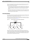
EtherChannel Port Groups
EtherChannel port groups treat multiple switch ports as one switch port. These port groups act as a single
logical port for high-bandwidth connections between switches or between switches and servers. An
EtherChannel balances the traffic load across the links in the channel. If a link within the EtherChannel
fails, traffic previously carried over the failed link changes to the remaining links.You can group
multiple trunk ports into one logical trunk port, group multiple access ports into one logical access port,
group multiple tunnel ports into one logical tunnel port, or group multiple routed ports into one logical
routed port. Most protocols operate over either single ports or aggregated switch ports and do not
recognize the physical ports within the port group. Exceptions are the DTP, the Cisco Discovery
Protocol (CDP), and the Port Aggregation Protocol (PAgP), which operate only on physical ports.