


1-23
Catalyst 3750-E and 3560-E Switch Software Configuration Guide
OL-9775-02
Chapter 1 Overview
Network Configuration Examples
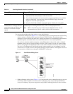
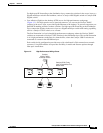
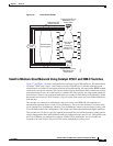
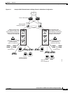
Figure 1-6 Linux Server Cluster
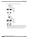
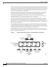
Small to Medium-Sized Network Using Catalyst 3750-E and 3560-E Switches
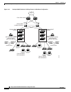
Figure 1-7 and Figure 1-8 show a configuration for a network of up to 500 employees. This network uses
a Catalyst 3750-E-only Layer 3 switch stack or Catalyst 3560-E Layer 3 switches with high-speed
connections to two routers. For network reliability and load-balancing, this network has HSRP enabled
on the routers and on the switches. This ensures connectivity to the Internet, WAN, and mission-critical
network resources in case one of the routers or switches fails. The switches are using routed uplinks for
faster failover. They are also configured with equal-cost routing for load sharing and redundancy. (When
the network uses Catalyst 3750-E switches, a Layer 2 switch stack can use cross-stack EtherChannel for
load sharing.)
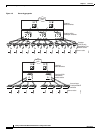
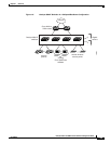
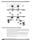
The switches are connected to workstations, and local servers, and IEEE 802.3af compliant and
noncompliant powered devices (such as Cisco IP Phones). The server farm includes a call-processing
server running Cisco CallManager software. Cisco CallManager controls call processing, routing, and
Cisco IP Phone features and configuration. The switches are interconnected through Gigabit interfaces.
This network uses VLANs to logically segment the network into well-defined broadcast groups and for
security management. Data and multimedia traffic are configured on the same VLAN. Voice traffic from
the Cisco IP Phones are configured on separate VVIDs. If data, multimedia, and voice traffic are
assigned to the same VLAN, only one VLAN can be configured per wiring closet.
200858
Campus
core
EtherChannel
across uplinks
Linux cluster
parallel-
processing
server farm
32-Gbps ring
Catalyst 3750-E-only
StackWise Plus
switch stack
Catalyst 3750-E-only
StackWise Plus
switch stack
Redundant SFP
module uplinks