


11-6
Catalyst 3750-E and 3560-E Switch Software Configuration Guide
OL-9775-02
Chapter 11 Configuring Interface Characteristics
Understanding Interface Types
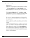
When you configure an EtherChannel, you create a port-channel logical interface and assign an interface
to the EtherChannel. For Layer 3 interfaces, you manually create the logical interface by using the
interface port-channel global configuration command. Then you manually assign an interface to the
EtherChannel by using the channel-group interface configuration command. For Layer 2 interfaces, use
the channel-group interface configuration command to dynamically create the port-channel logical
interface. This command binds the physical and logical ports together. For more information, see
Chapter 37, “Configuring EtherChannels and Link-State Tracking.”
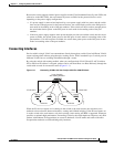
10-Gigabit Ethernet Interfaces
The Catalyst 3750-E and 3560-E switches have two 10-Gigabit Ethernet module slots. For uplink
connections to other switches and routers, use the Cisco TwinGig Converter Modules.
A 10-Gigabit Ethernet interface operates only in full-duplex mode. The interface can be configured as a
switched or routed port.
For more information about the Cisco TwinGig Converter Module, see the switch hardware installation
guide and your transceiver module documentation.
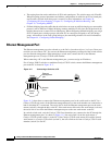
Power over Ethernet Ports
A PoE-capable switch port automatically supplies power to one of these connected devices if the switch
senses that there is no power on the circuit:
• Cisco pre-standard powered device (such as a Cisco IP Phone or a Cisco Aironet Access Point)
• IEEE 802.3af-compliant powered device
Each 10/100/1000 PoE port provides up to 15.4 W of power to the device.
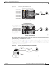
A powered device can receive redundant power when it is connected to a PoE switch port and to an AC
power source. The device does not receive redundant power when it is only connected to the PoE port.
After the switch detects a powered device, the switch determines the device power requirements and then
grants or denies power to the device. The switch can also sense the real-time power consumption of the
device by monitoring and policing the power usage.
This section has this PoE information:
• Supported Protocols and Standards, page 11-6
• Powered-Device Detection and Initial Power Allocation, page 11-7
• Power Management Modes, page 11-8
• Power Monitoring and Power Policing, page 11-9
Supported Protocols and Standards
The switch uses these protocols and standards to support PoE:
• CDP with power consumption—The powered device notifies the switch of the amount of power it
is consuming. The switch does not reply to the power-consumption messages. The switch can only
supply power to or remove power from the PoE port.
• Cisco intelligent power management—The powered device and the switch negotiate through
power-negotiation CDP messages for an agreed-upon power-consumption level. The negotiation
allows a high-power Cisco powered device, which consumes more than 7 W, to operate at its highest