


User Guide NetXtreme II
January 2010
Broadcom Corporation
Document ENGSRVT52-CDUM100-R General Network Considerations Page 39
GENERAL NETWORK CONSIDERATIONS
• Teaming with Microsoft Virtual Server 2005
• Teaming Across Switches
• Spanning Tree Algorithm
• Layer 3 Routing/Switching
• Teaming with Hubs (for troubleshooting purposes only)
• Teaming with Microsoft NLB
TEAMING WITH MICROSOFT VIRTUAL SERVER 2005
The only supported BASP team configuration when using Microsoft Virtual Server 2005 is with a Smart Load Balancing (TM)
team-type consisting of a single primary Broadcom adapter and a standby Broadcom adapter. Make sure to unbind or
deselect “Virtual Machine Network Services” from each team member prior to creating a team and prior to creating Virtual
networks with Microsoft Virtual Server. Additionally, a virtual network should be created in this software and subsequently
bound to the virtual adapter created by a team. Directly binding a Guest operating system to a team virtual adapter may not
render the desired results.
NOTE: As of this writing, Windows Server 2008 is not a supported operating system for Microsoft Virtual Server
2005; thus, teaming may not function as expected with this combination.
TEAMING ACROSS SWITCHES
SLB teaming can be configured across switches. The switches, however, must be connected together. Generic Trunking
and Link Aggregation do not work across switches because each of these implementations requires that all physical
adapters in a team share the same Ethernet MAC address. It is important to note that SLB can only detect the loss of link
between the ports in the team and their immediate link partner. SLB has no way of reacting to other hardware failures in the
switches and cannot detect loss of link on other ports.
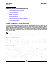
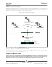
Switch-Link Fault Tolerance
The diagrams below describe the operation of an SLB team in a switch fault tolerant configuration. We show the mapping
of the ping request and ping replies in an SLB team with two active members. All servers (Blue, Gray and Red) have a
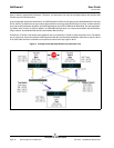
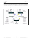
continuous ping to each other. Figure 3 is a setup without the interconnect cable in place between the two switches. Figure 4
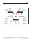
has the interconnect cable in place, and Figure 5 is an example of a failover event with the Interconnect cable in place. These
scenarios describe the behavior of teaming across the two switches and the importance of the interconnect link.
The diagrams show the secondary team member sending the ICMP echo requests (yellow arrows) while the primary team
member receives the respective ICMP echo replies (blue arrows). This illustrates a key characteristic of the teaming
software. The load balancing algorithms do not synchronize how frames are load balanced when sent or received. In other
words, frames for a given conversation can go out and be received on different interfaces in the team. This is true for all