


1-60
Cisco Media Gateway Controller Software Release 9 Billing Interface Guide
OL-1089-11
Chapter 1 Billing Interfaces
CDE Detail Description
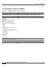
Nature of Connection Indicators Received (Tag: 2011/ANSI)
Table 1-34 Nature of Connection Indicators Received Description Form
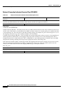
Name: Nature of Connection Indicators
Received
Tag: 2011 Source: MDL
Description/Purpose: Used to record the Nature of Connection received from the IAM. Three possible indicators can be
received: the satellite indicator, the continuity check indicator, and the echo suppressor indicator.
Format: ANSI T1.113 Length in Octets: 1
Data Value:
Assume bit order HGFEDCBA
Satellite Indicator (Bits BA)—This field provides the Cisco MGC with information on how many satellites have been used
on this circuit. If the field is set to 00 and the Cisco MGC sends the circuit out on a circuit going over a satellite, the field
is incremented by one. The same goes for the other incoming settings (for example, 01 goes to 10 and 10 goes to 11). If
the outgoing circuit doesn't go over a satellite, the field is not incremented.
Continuity check indicator (Bits DC)—The Cisco MGC acts upon this field based on what is received. Also depending on
mutual agreements with the LECs, each outgoing trunk group sends Continuity tones to the terminating LECs with a
frequency between 0% to 100% of the time. This is configurable on a per trunk group basis. In addition, the Cisco MGC
interprets the incoming continuity field and passes the appropriate action to the Coding Unit.
Echo suppressor indicator (Bit E)—If this field is filled, the outgoing half echo control is already set on previous circuits,
there is no need for the terminating Cisco MGC to engage the EC. for this call. If the Cisco MGC activates the echo
canceller, this field needs to be set for the outgoing IAM message to subsequent switches.
Bits F-G: spare
Extended Data Value:
General Information:
MGC Release: Release 5.0 and later.