


5/26/05 Monitoring Channels on a Floor Map
OL-7426-03
Monitoring Channels on a Floor MapMonitoring Channels on a Floor Map
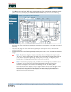
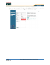
Use MONITOR/Maps, click an item in the Name column, double-click the floor map, from the Display
drop-down menu, select Channel to access this page.
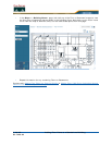
When you select this option, the channel number being used by the Cisco Radio is displayed on the
panel next to each Cisco 1000 Series lightweight access point. This display depends upon the selection
made from the Protocol pulldown as follows:
• 802.11a: The display shows the channel: Ch#n, where n is the channel number.
• 802.11b/g: The display shows the channel: Ch#n, where n is the channel number.
• 802.11a and 802.11b/g: The display shows the channels in the following format: Ch#n/x,
where n represents the channel being used by the 802.11a Cisco Radio and x represents the
channel being used by the 802.11b/g Cisco Radio.
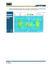
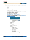
Monitoring Transmit Power Levels on a Floor MapMonitoring Transmit Power Levels on a Floor Map
Use MONITOR/Maps, click an item in the Name column, double-click the floor map, from the Display
drop-down menu, select Tx Power Level to access this page.
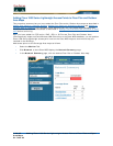
When you select this option, the power level number being used by the Cisco Radio is displayed on the
panel next to each Cisco 1000 Series lightweight access point.
Power Level (1, highest through 5, lowest) Cisco 1000 Series lightweight access point transmit power
level are as follows:
• 1 = Maximum power allowed per Country Code setting
• 2 = 50% power
• 3 = 25% power
• 4 = 6.25 to 12.5% power
• 5 = 0.195 to 6.25% power
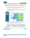
The power levels and available channels are defined by the Country Code setting and are regulated on
a country by country basis. Refer to Cisco WLAN Solution Supported Country Codes for the maximum
Transmit Power Levels for each country.
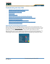
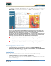
Monitoring Coverage Holes on a Floor MapMonitoring Coverage Holes on a Floor Map
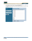
Use MONITOR/Maps, click an item in the Name column, left-click the floor map, from the Display
drop-down menu, select Coverage Holes to access this page.
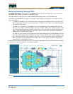
In the Alarm Monitor, click on a colored Coverage alarm to access this page.
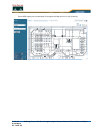
Coverage holes are areas where clients cannot receive a signal from the wireless network. When
deploying wireless networks, there is a trade-off between the cost of the initial network deployment
and the percentage of coverage hole areas. A reasonable coverage hole criterion for launch is between
2 and 10 percent. This means that between two and ten test locations out of 100 random test locations
may receive marginal service. After launch, the Cisco WLAN Solution Radio Resource Management
(RRM) identifies these coverage areas and reports them to the IT manager, allowing the IT manager to
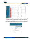
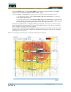
fill holes based on user demand. This percentage is shown in the panel next to each Cisco 1000 Series
lightweight access point on the map. They are displayed as follows:
• 802.11a: The display shows the coverage hole percentage for this Cisco Radio.
• 802.11b/g: The display shows the coverage hole percentage for this Cisco Radio.
• 802.11a and 802.11b/g: The display shows the total coverage hole percentage for both Cisco
Radios.