


B-11
Cisco uBR924 Software Configuration Guide
OL-0337-05 (8/2002)
Appendix B Using the Cable Monitor Tool
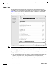
Sample Pages
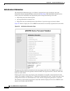
• Reset state—The router boots the Read-Only Memory (ROM) from its Flash memory, performs a
self-test, initializes processor hardware, and boots the Cisco IOS release image stored in Flash
memory.
• Wait for link up state—The router checks the cable interface and determines whether a
DOCSIS-compliant signal exists.
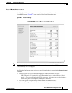
• Downstream frequency scanning state—The router acquires a temporary downstream channel by
matching the clock sync signal that is regularly sent out by the CMTS in the downstream frequency
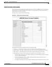
range. If this stage passes, click this link to display the following information:
–
Downstream ID
–
Downstream Frequency
–
Downstream Symbol Rate
–
Downstream QAM Mode
–
Signal to Noise Ratio Estimate
–
Downstream Lock Threshold
–
Downstream Search
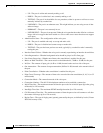
• Wait for Upstream Channel Descriptor (UCD) state—The router waits for an Upstream Channel
Descriptor (UCD) message from the CMTS and configures itself for the upstream frequency
specified in that message. If this stage passes, click this link to display the following information:
–
Upstream ID
–
Upstream Frequency
–
Mini-Slot Size
• Wait for MAP state—The router waits for the next upstream bandwidth allocation map message
(MAP), which are regularly sent from the CMTS, to find the next available shared request timeslot.
• Power ranging first state—The router then uses the MAP timeslot to send a ranging request message
to the CMTS, communicating the router's user ID (UID, which is its unique MAC address), using a
temporary Service Identifier (SID) of 0 (zero) to indicate it has not yet been allocated an upstream
channel. If this stage passes, click this link to display the following information:
–
Ranging Offset
–
Power Level
–
Ranging Response SID Assigned
–
Adjust Transmit Power
• Power ranging second state—In reply to the router's ranging request, the CMTS sends a ranging
response containing a temporary SID to be used for the initial router configuration and bandwidth
allocation. As needed, the router adjusts its transmit power levels using the power increment value
given by the CMTS in its ranging response message.
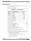
• DHCP state—After the next MAP message broadcast, the router uses a shared require timeslot to
invoke the Dynamic Host Configuration Protocol (DHCP) to establish IP connectivity with the
TCP/IP network at the headend. The DHCP server sends a response with the following information:
–
Assigned IP Address
–
Network Mask
–
TFTP Server IP Address
–
Time Server IP Address