


4-12
Cisco uBR924 Software Configuration Guide
OL-0337-05 (8/2002)
Chapter 4 Voice over IP Configurations
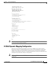
H.323v2 Dynamic Mapping Configuration
The example shown in this section assumes that Cisco Network Registrar (CNR) version 3.0 or higher
is being used as the DHCP server. CNR assigns the E.164 addresses to local voice ports and uses DHCP
to define the E.164 addresses-to-port assignments.
The gatekeeper can be a Cisco router, such as the Cisco 3620, with a Cisco IOS image that supports the
gatekeeper function. The Cisco uBR924 router acts as the H.323v2 gateway and creates the dial peers,
starts H.323 RAS gateway support, and registers the E.164 addresses with the gatekeeper. The
gatekeeper resolves the remote peers’ IP addresses when the router sends a request using RAS.
Note Support for RAS and H.323v2 in Cisco gatekeeper products is found in Cisco IOS Release 12.0(5)T or
higher. Support for multiple classes of service when using Cisco uBR7200 CMTS equipment is found in
Cisco 12.0(4)XI or higher.
If you are not using CNR or Cisco gatekeeper products running Cisco IOS Release 12.0(5)T software,
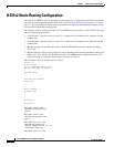
use a static dial-map as shown in the previous H.323 configurations (“H.323v2 Static Bridging
Configuration” and “H.323v2 Static Routing Configuration”).
You must do the following to configure the Cisco uBR924 router for dynamic mapping:
• Configure the local dial-peers—This is done in the same way as for a static H.323v2 dial map.
• Configure the remote dial-peers—This is done in the same way as for a static H.323v2 dial map,
except that instead of specifying a target IP address or host name, you specify ras as the target.
• Enable the VoIP gateway function using the gateway global configuration command.
• Configure the cable modem interface to be the gateway interface.
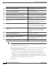
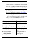
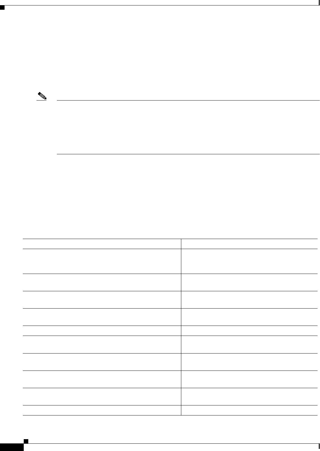
These functions are done using the commands shown in the following table:
Command Purpose
Step 1
To configure incoming calls on voice port V1:
uBR924(config)# dial-peer voice id-number pots Specify a unique id-number for this incoming
dial-peer and enter dial-peer configuration mode.
Step 2
uBR924(config-dial-peer)# destination-pattern digits Specify the telephone number(s) associated with this
voice port.
Step 3
uBR924(config-dial-peer)# port 0 Specify that voice port V1 is attached to this
telephony equipment.
Step 4
uBR924(config-dial-peer)# dtmf-relay [cisco-rtp]
[h245-signal] [h245-alphanumeric]
Optionally configure the dial peer to support out of
band signaling of DTMF tones.
Step 5
uBR924(config-dial-peer)# exit Exit dial-peer configuration mode.
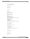
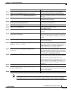
Step 6
To configure incoming calls on voice port V2:
uBR924(config)# dial-peer voice id-number pots
Specify a unique id-number for this incoming
dial-peer and enter dial-peer configuration mode.
Step 7
uBR924(config-dial-peer)# destination-pattern digits Specify the telephone number(s) associated with this
voice port.
Step 8
uBR924(config-dial-peer)# port 1 Specify that voice port V2 is attached to this
telephony equipment.
Step 9
uBR924(config-dial-peer)# dtmf-relay [cisco-rtp]
[h245-signal] [h245-alphanumeric]
Optionally configure the dial peer to support out of
band signaling of DTMF tones.
Step 10
uBR924(config-dial-peer)# exit Exit dial-peer configuration mode.