


4-7
Cisco uBR924 Software Configuration Guide
OL-0337-05 (8/2002)
Chapter 4 Voice over IP Configurations
H.323v2 Static Bridging Configuration
H.323v2 Static Bridging Configuration
When the Cisco uBR924 router is running in DOCSIS-bridging mode and using a Cisco IOS image with
voice support, it can route voice calls using an H.323v2 static dialing map. This requires the following
minimum configuration:
• Create a local dial peer for each voice port that will receive incoming calls. This requires configuring
each voice port on the router with the phone numbers for the devices attached to those voice ports.
The Cisco uBR924 router uses these numbers to determine which voice port should receive the call.
Typically, the complete phone number or extension is specified for each port; when the
Cisco uBR924 router receives an incoming call, all digits in the number are matched and stripped
off, and the voice port is connected to the call.
Note The voice ports on the Cisco uBR924 router support only FXS devices.
• Configure a remote dial peer for each possible destination for outgoing calls. This requires
specifying the phone number(s) for the destination devices. Use the following guidelines for what
numbers to enter:
–
For a single telephony device, such as a one-line phone or fax machine, enter the complete
phone number or extension.
–
To direct a group of numbers to a specific destination—such as the extensions used on a remote
PBX—enter a pattern matching the prefix used for those lines; asterisks can be used to match
any number of digits and a period matches a single digit. For example, “572*” matches any
phone numbers starting with 572 while “572.” matches the numbers 5720–5729.
You must also specify the IP address for the destination host that will deliver the call to the telephony
device (or if the destination device is an IP telephone, the IP address for that telephone). You can
optionally specify an IP precedence level for the type of service (ToS) bits in the IP header to signify
that these voice packets should be given higher priority in transit across the IP network.
If not being done by the CoS, you can also specify which coding/decoding (CODEC) algorithm
should be used.
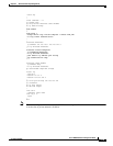
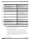
These functions are done using the dial-peer command, as shown in the following table:
Command Purpose
Step 1
To configure incoming calls on voice port V1:
uBR924(config)# dial-peer voice id-number pots Specify a unique id-number for this incoming
dial-peer and enter dial-peer configuration mode.
Step 2
uBR924(config-dial-peer)# destination-pattern digits Specify the telephone number(s) associated with this
voice port.
Step 3
uBR924(config-dial-peer)# port 0 Specify that voice port V1 is attached to this
telephony equipment.
Step 4
uBR924(config-dial-peer)# dtmf-relay [cisco-rtp]
[h245-signal] [h245-alphanumeric]
Optionally configure the dial peer to support out of
band signaling of DTMF tones.
Step 5
uBR924(config-dial-peer)# exit Exit dial-peer configuration mode.
Step 6
To configure incoming calls on voice port V2:
uBR924(config)# dial-peer voice id-number pots Specify a unique id-number for this incoming
dial-peer and enter dial-peer configuration mode.
Step 7
uBR924(config-dial-peer)# destination-pattern digits Specify the telephone number(s) associated with this
voice port.