


Technical Reference Guide
Compaq Deskpro EN Series of Personal Computers
Desktop and Minitower Form Factors
Third Edition - September 1998
5-9
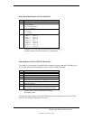
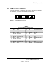
5.3 DISKETTE DRIVE INTERFACE
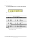
The diskette drive interface supports up to two diskette drives, each of which connect to a
standard 34-pin diskette drive connector. All models come standard with a 3.5-inch 1.44-MB
diskette drive installed as drive A. An additional diskette drive (either a 3.5-inch 720-KB, 1.44-
MB, or 2.88-MB drive or a 5.25-inch 360-KB or 1.2-MB drive) may also be installed as drive B.
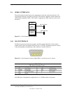
The drive designation is determined by which connector is used on the diskette drive cable. The
drive attached to the end connector is drive A while the drive attached to the second (next to the
end) connector) is drive B.
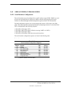
On all models, the diskette drive interface function is integrated into the 87307 I/O controller
component. The internal logic of the I/O controller is software-compatible with standard 82077-
type logic. The diskette drive controller has three operational phases in the following order:
♦ Command phase - The controller receives the command from the system.
♦ Execution phase - The controller carries out the command.
♦ Results phase - Status and results data is read back from the controller to the system.
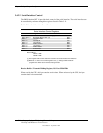
The Command phase consists of several bytes written in series from the CPU to the data register
(3F5h/375h). The first byte identifies the command and the remaining bytes define the
parameters of the command. The Main Status register (3F4h/374h) provides data flow control
for the diskette drive controller and must be polled between each byte transfer during the
Command phase.
The Execution phase starts as soon as the last byte of the Command phase is received. An
Execution phase may involve the transfer of data to and from the diskette drive, a mechnical
control function of the drive, or an operation that remains internal to the diskette drive controller.
Data transfers (writes or reads) with the diskette drive controller are by DMA, using the DRQ2
and DACK2- signals for control.
The Results phase consists of the CPU reading a series of status bytes (from the data register
(3F5h/375h)) that indicate the results of the command. Note that some commands do not have a
Result phase, in which case the Execution phase can be followed by a Command phase.
During periods of inactivity, the diskette drive controller is in a non-operation mode known as
the Idle phase.