


Chapter 2 System Overview
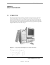
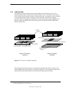
Compaq Deskpro EN Series of Personal Computers
Desktop and Minitower Form Factors
Third Edition – September 1998
2-8
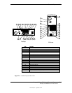
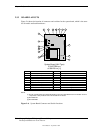
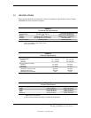
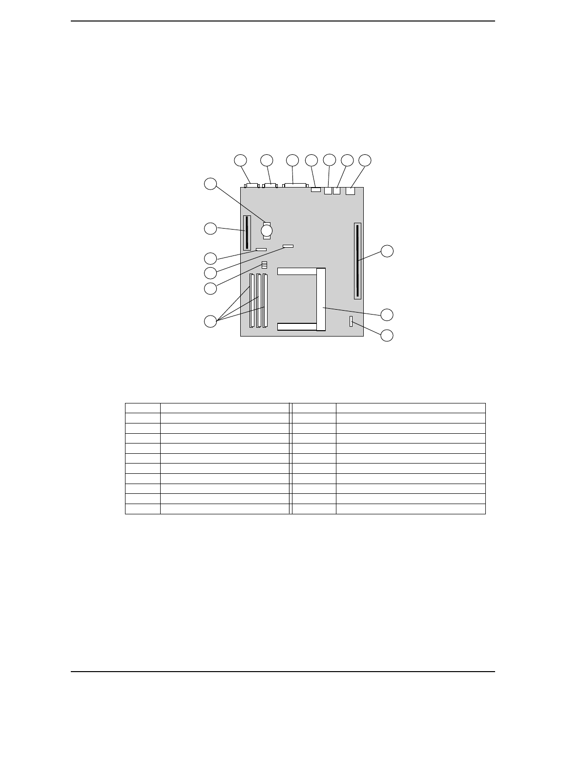
2.3.3 BOARD LAYOUTS
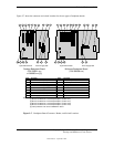
Figure 2-6 shows the location of connectors and switches for the system board, which is the same
for all models and both formfactors.
Item Function Item Function
1 Serial I/F (COM2) 7 (bottom) USB Port A I/F
2 Serial I/F (COM1) 8 Backplane Connector
3 Parallel I/F 9 Processor Slot 1
4 (top) Mouse connector 10 Heat Sink Thermal Diode Connector [2]
4 (bottom) Keyboard connector 11 DIMM Sockets
5 (top) Audio Line Input 12 Frequency/Password DIP Switch
5 (bottom) Audio Line Output 13 Heat Sink Thermal Diode Connector [3]
6 (top) Audio Mic Input 14 CMOS Clear Jumper
6 (bottom) Audio Headphone Output 15 AGP Slot (NLX-type)
7 (top) USB Port B I/F 16 Battery
NOTE:
[1] The two system boards are electrically identical. There are slight differences in the location of some
components. Later production units use the 008123-xxx board.
[2] PCA # 008123
[3] PCA # 007998
Figure 2–6.
System Board Connector and Switch Locations
System Board (NLX-Type)
1 3
4
5
2
8
9
6 7
(P/N 007998-xxx
or 008123-xxx [1])
11
12
13
14
15
16
10