


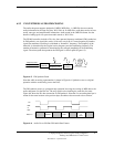

Technical Reference Guide
Compaq Deskpro EN Series of Personal Computers
Desktop and Minitower Form Factors
Third Edition - September 1998
7-3
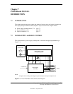
7.2.2 POWER CONTROL
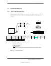
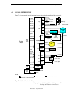
The power supply assembly is controlled digitally by the PS On signal (Figure 6-1). When PS On
is asserted, the Power Supply Assembly is activated and all voltage outputs (+3 VDC, +5 AUX,
+/-5 VDC, +/-12 VDC) are produced. When PS On is de-asserted, the Power Supply Assembly is
off and all voltages (except +5 AUX) are not generated. Note that +5 AUX is always produced as
long as the system is connected to a live AC source (as indicated by an illuminated system board
LED).
7.2.2.1 Power Button
The PS On signal is typically controlled through the Power Button which, when pressed and
released, applies a negative (grounding) pulse to the power control logic. (Refer to section 7.2.2.3
for PS On control select.) The resultant action of pressing the power button depends on the state
and mode of the system at that time and is described as follows:
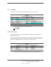
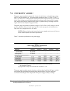
System State Pressed Power Button Results In:
Off Negative pulse, of which the falling edge results in power control logic asserting
PS On signal to Power Supply Assembly, which then initializes. ACPI four-
second counter is not active.
On, ACPI Disabled Negative pulse, of which the falling edge causes power control logic to de-assert
the PS On signal. ACPI four-second counter is not active.
On, ACPI Enabled Pressed and Released Under Four Seconds:
Negative pulse, of which the falling edge causes power control logic to
generate SMI-, set a bit in the SMI source register, set a bit for button status,
and start four-second counter. Software should clear the button status bit
within four seconds and the Suspend state is entered. If the status bit is
not cleared by software in four seconds PS On is de-asserted and the
power supply assembly shuts down (this operation is meant as a guard if
the OS is hung).
Pressed and Held At least Four Seconds Before Release:
If the button is held in for at least four seconds and then released, PS On is
negated, de-activating the power supply.
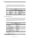
7.2.2.2 Power LED Indications
Two LEDs are used to indicate system power status. The front panel (bezel) power LED provides
a visual indication of three key system conditions listed as follows:
Power LED Condition
Steady On Normal full-on operation
Blinking @ 1 Hz Sleep (suspend) state
Blinking @ 4 Hz Thermal condition: processor has overheated and shut down
An additional LED is mounted on the system board. This LED is connected to the +5 AUX bus
and will be on as long as the system unit is connected to live AC power
regardless of the status
of the PS On signal
. The AC line cord should always be disconnected and the system board LED
should
not
be illuminated before servicing the unit.